When you click on links to various merchants on this site and make a purchase, this can result in this site earning a commission. Affiliate programs and affiliations include, but are not limited to, the eBay Partner Network.
ALL DONE !!!!
Keyless Go and Rear SAM.
Have not started engine but have tried key position 2 ready to crank...all good.
Waiting for my epoxy to dry tomorrow, that damn spare tyre plastic thingy which cracked.
U have a scope Cali ? U want to scope the CAN-B ?
I have a low end beginner 25 Mhz Pico 2205A 2 channel coming in a month or so.
This is non automotive, but can hack the PC software to use Pico Automotive 6 . Got the 20:1 attenuator from Hantek, so no more locked to 20 Volt.
I want to use it among others to read/see the CAN signal, more so for the headlights high beam command.... I am still curious.
Congrats for completing your trunk resoldering. The more we discover, the more we learn!
I have 2x dual-channel scopes 10x probe on my original analog era for lab work over a bench and my latest geek tool: a linux based digital scope for going around in my shirt pocket! 🙂
scope arsenal
Wish I had Xentry but for now I use what I have around until next step.
My DS212 (eBay/AMZ ?)
+++ Testing report & conclusions: moved 1 post down in #54
✌️
Last edited by CaliBenzDriver; 07-14-2021 at 03:16 PM.
Reason: I think... therefore I am - WS.
I have not try it , maybe later I will. The Rear SAM is still naked. I have not place back the liner.
I found my 10 years old or so temperature controlled Goot RX-711AS Soldering Station. I never use this much, until now with Rear SAM. Quite a learning experience using this solder for a few hours.
This solder is very sensitive to heat loss. This is the unique part. It is so precise in the temperature control, overall it does not overheat the connectors compared to my usual multi purpos Goot TQ-77 20/200watt.
While other pins except these 4 below, only need 5 seconds contact to heat up, these 4 pins spread the heat to the copper trace need a lot more time.
Usually for soldering wires of 1.5mm to 2.5mm ( what I solder most ) I use my favourite 20/200 Watt Goot TQ 77, this one :
Double magnifying glass required, my eyes so bad. I almost short circuit these two pins during first 1 hour on the job .... LOL.
Later I got the hang of it, and things improved. Been 15+ years I really did any soldering, but none this small size and many solder points grouped so close together.
This sucker saved the day. Beats using the spring operated solder suction gun. Another 10+ years old asset. I got these two Goot precision soldering stuff was for my dive computer battery change mid year 2000s.
Never expected it will come handy this week.
The Keyless Go part, me have burned some experience hours from Rear SAM and it was much easier.
Very short pins and heat transfer not as fast as the longer pins of R-SAM, but okey.
Will I do this R-SAM soldering again ? NO..... ha ha ha. If possible no.
I have to admit, my fingers are not made for small stuff soldering. Even anything less than 10mm bolt is too small for me ....
My last real soldering adventure , I soldered every damn crimped connector on my co-own boat. It was 2004 to 2007 fun project of re-powering from 2 x 275 HP diesel inboards to 3 x 250HP outboards, 1.6 meters hull extended too.
A hundred plus end points of 1.5mm , 2.5mm wires and many batttery wire size too. I rewired the entire boat. Its an old 1995 boat.
Soldering big battery wire crimped connector is a bi-etch.... indeed. Port and Starboard Engine starting battery.
This is a wonderful set of soldering tools you have. I tend to use leaded trouble-free solder as well
I really like your stainless boating nuts+bolts hardware for long lasting dependability in corrosive environment. Nicely labeled for documentation. I've industrial panels where wires are labeled with Numbers registered on a schematic.
The issue is always what is the best way to troubleshoot a complex system? There are many-many ways and every honest individual uses its on preferred method to turn up a fix, a profit and sometimes even both.
+++++++++++++ Reflection on yoyo chaos : +++++++++++
Crazy charge, flakey modules... all bad GND:
The rework accomplished so far yields a strong voltage control with minimal currents but still does not eradicate 11VDC swings.
Don't through away the baby with the bathwater....
Based on what I have observed, the battery charge logic does work textbook fine even on impacted cars. The uncontrolled discharge happens when float voltage crashes a particular CAN module that was already borderline undervolted by a painted GND.
While this style of chaos is simple to fix ("$3 worth") it is hard to pinch because it disrupts part of the system COM's. When that happens R-SAM is no longer able to properly control float voltage so voltage and currents go out of control in a 14.9 > 11.x yoyo.
Banging on CAN-B string:
- My assumption more than ever is the problem is caused by poor connections (painted GND, solderless Pins)... Now the question is where?
To progress without having a specific target, I encompass the entire CAN group that involves my suspects: CAN-B. Noting that my RFK has always been packing DTC's (direct GND on wheelwell) that complain about broken chat across gateway (F-SAM/CGW).
Tracking Forward:
Sanitized poor connections in the Trunk are a prerequisite for further work... so I'd say Just Do-It
1_ Sanitized Trunk modules
2_ F-SAM:GND
3_ Cabin:
- Modules GND + Solderless pin: fix complete!?
prime suspects are CAN-B modules
++++++
At some point I am going to get interested to Brake Switch Live Data reporting: 10.5VDC... is that the voltage source that trips over 12.6 turning that into 8VDC.
Under-volted CAN-Hi mixed with Floating CAN-Lo.... may well be the name of this chaos opportunity.
Who wants to bet the bad CAN node lives in F-SAM?
Getting a diagram of ground points with location would be greatly appreciated
✌️
Last edited by CaliBenzDriver; 07-14-2021 at 11:14 PM.
Reason: GROUNDED BY SATURDAY ?
OBD data source is Banks Data Monster gauge at 1 Hz logging.
This time I use Race Render video editor to insert 45 seconds Voltages graph.
The graph and live video help me to understand better what I was doing when these voltage dips occured.
Attached the excel file used as the OBD data source.
Video frame to OBD data shown, the accuracy will be with <1 second , I can guarantee that.
When watching instrument cluster Voltage and Amperage, do remember that the amperage is not the GROSS output of the alternator , but the amperage that goes into/out-of the battery.
However, since the alternator is in "parallel" to the battery, the way we look at the current draw as shown on the instrument cluster amperage gauge should be visualized like this :
Alternator and battery is like 2 generators in sync.
However, speed of response of battery is way faster than an alternator towards amperage demand.
In other words, the battery is always the one taking the beating 1 or 2 seconds ahead when a sudden high discharge occurs.
Instrument cluster Voltage data , I have to assume its point of sensing to be at Front SAM but at a very upstream source, perhaps it is very close to
the terminal Pin 16S at Front SAM, 16mm wire from MR7 of F32 prefuse.
This is the biggest wire size to Front SAM and not via K2 Relay of F32 prefuse.
To note, I have disconnected the B95 battery sensor 2 data wires and only amperage data lost but not voltage data.
So it remains a mystery for now, where is the EXACT location/spot for voltage sensing for ECO charging algo and is that spot the same for voltage data of instrument cluster ?
If one only rely on ONLY Instrument Cluster voltage information and not looking at ECU voltage and Rear SAM ( via OBD port pin #16 ), we can't see the whole story.
The whole story is about potential localized low voltage at every device or SAMs where voltage stability matters a great deal for either engine performance or
data stream reliability...whatever.
I also think the engineering team who made the algo failed to realize that sustain discharging on a battery and at at certain threshold of amperage drain percentage vs the battery Ah rating,
sudden voltage drop will occur , no way to avoid that even on AGM. If Lithium Ion is different, it can do insane discharge and still offer stable* voltage. *Based on my drone called 3DR Solo, WOT for take off at 400 watts.
14.8 volt battery and only 5.2 amps hour. Sucked at 400 watts or 27 amps ( 500% of it Ah rating ) and voltage drop is so decent. This battery can even do up to 120A burst discharge...dang, 2,300% of its Ah rating.
Take any full charged 90Ah AGM, do 35 amps discharge and see how voltage will dip for sure, discharge it at 5 amps and it won't dip down so bad.
If only the algo takes multiple voltage sensing points, say one at ECU, one at Rear SAM and one more where it is NOW taking voltage data from, called it X spot.... and
enforce no voltage dip allowed under 12.5V at any 3 locations and also do not discharge higher than 10 amps, the voltage dip would be minimized and we all the
"****-yzer" will be smiling
Thank you Surya for taking us out on a very smart test drive.
👍 👍
Personally for me the fact that I've observed less than 11.7Volts while driving tells me the discharge is bottom less until ECU/TCM crash the engine.
It does not stop discharging around 12.3v, nop!
If you give it enough stable driving speed without 14.9 burst, it will dangerously empty your AGM. Beware when driving drained battery.
Bottomless deep discharge is not managed by an algorithm trying to hold charge around 80% to save gasoline.
It is the charging system loosing ability to remote control the ALT output during the 12.6v float period, after driving a while.
I have seen my German lemon do just fine floating 12.6v, bursting 14.9v, pegging headlights and A/C voltage... textbook perfect until it quits being smart.
We have a great many questions with unknown answers (cluster VDC display, etc...).
We can only stand on what we know and what we see by testing.
Based on that mix, my hypothesis is F-SAM may be holding a surprise.
Skewing a resistive GND Reference takes some heavy current load... F-SAM has just that with A/C runing and the car 30Amp base demand. That makes it my next GND-Cleaning recipient.
Process of elimination:
I now trust R-SAM (Pins/GND) and we are sanitizing CAN-B modules so they can't fload their gateway that happens to be shared by R-SAM to do its 12.6v float control.
Patience, we're almost there! F-SAM side by side MCU.
I don't have specific documentation but it sure looks to me like 2x co-hosted I/O modules.
This Bosch control unit acts as the butler of MAIN ECU... it better be in top shape.
Last edited by CaliBenzDriver; 07-15-2021 at 09:25 PM.
Cali wrote : Getting a diagram of ground points with location would be greatly appreciated
Attached all I got on ground points
Remarks I made on the document title is a reminder for me on M276 3.0 TT and being a right hand drive car.
Thank you DIVE Master 👍
With all that doc, we can get deep down to the bottom of this thing - Trust me I am/was licenced advanced PADI rescue diver, "recreational" only not an oil-rig diving welder like Fred in the GoldRush
Do you watch "Gold Rush: White Waters" show in the Alaska Ukon diving up high in the mountain creek?
See old man Fred "The Crew Finds A Nugget Trap Full Of Gold! | Gold Rush: White Water" on YouTube... https://youtu.be/iF-Cio1WYLI
The man teaches strong resolve
Last edited by CaliBenzDriver; 07-15-2021 at 07:06 PM.
Jul 15 Update
1 - 4 trunk GND points brushed and cleaned with DeoxIt (100%), paint sanded out of the post, and nut base.
2 - RearSAM soldered, and apparently I did not short anything , hopefully, they are OK. I had to redo a few ones after I zoomed in the pictures (and forgot to retake photos)
3 - All back in the car, no sparks in between
4 - The car started with no surprises so far.
5 - TODO: a test drive
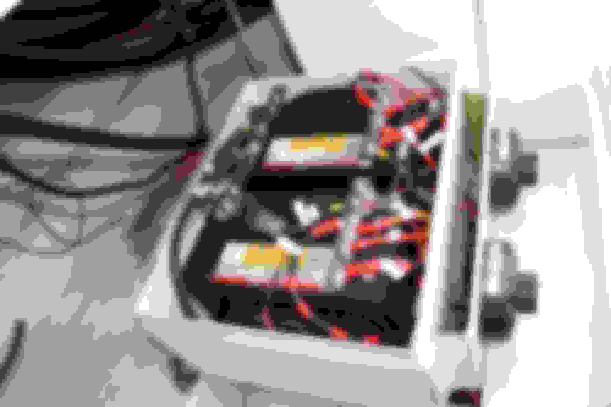
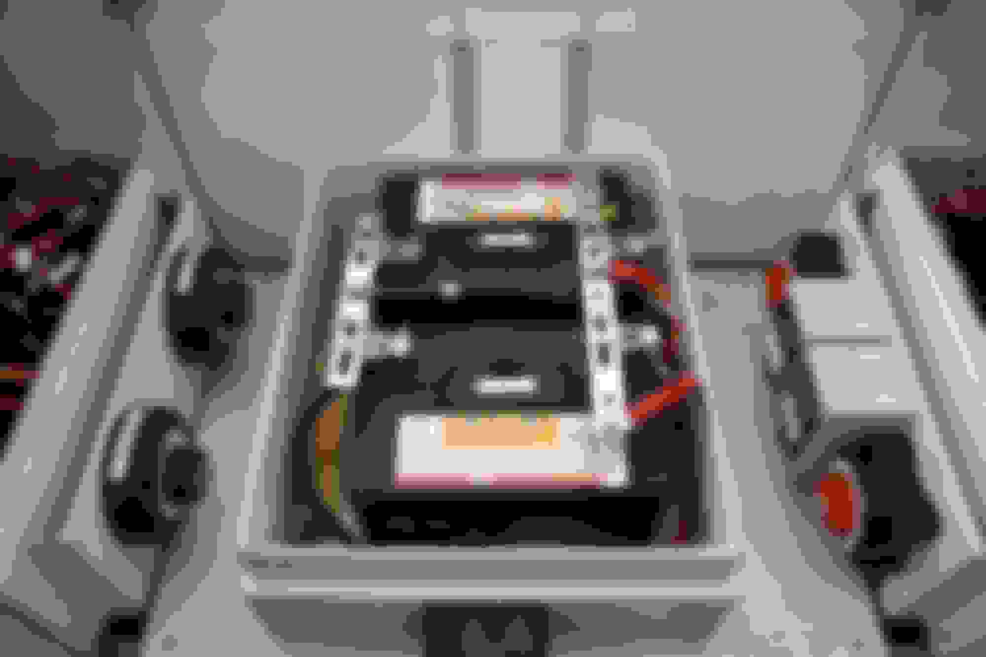
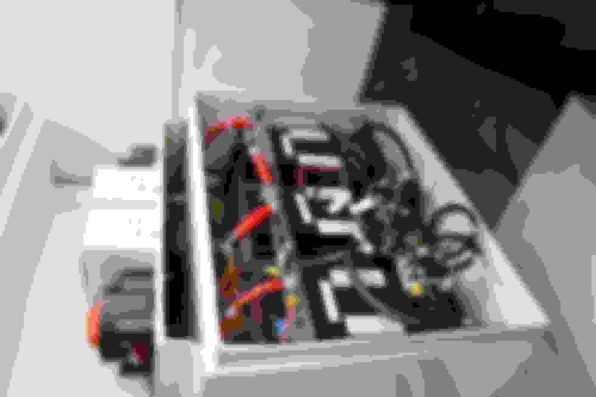
Pictures of soldered RearSAM - Full view
Bottom Left
Bottom Right
Top view:
It took me like 4 tries on those 4 at the top left of this view. I got like spheres of solder barely touching the board.
Pretty good looking results there! The solder ***** happen when temperature is not homogenous, usually cold spots. So you heat up a bit more within measure!!
👍
When the limits are well defined its up to us to watch out so nothing wrong happens like a solder bridge. 10mn close inspection is a cheap insurance.
Soldering pins is always a better choice than dealing with a sick module with proprietary chips.
++++++++++
Do you want to enlist in the hunt for additional solderless CAN-B modules??
4x Doors
2x Front Seats
1x Rear Seat module cache
Driver footwell
Passenger footwell
Central console
Overhead console (known soldered)
Engine bay (US Driver - LHD)
Engine bay (US Passenger - RHD)
🤗
Last edited by CaliBenzDriver; 07-15-2021 at 09:22 PM.
Reason: candidate locations
So your 11.7V is based on Instrument Cluster data.... right ?
Do you have any data from OBD2 : ECU voltage and OBD Bus voltage aka Rear SAM but with stupidly small 0.75mm wire to OBD port pin 16.
Mercedes called the OBD port as X11/4 diagnostic port.
Attached their 2 PDF.
My car OBD port :
As I explained before :
01. ECU voltage is digital/software, sent by ECU into CAN BUS and decoded by OBD Gauge.
02. OBD Bus voltage is analog, so its accuracy may depend on how the OBD Gauge measure analog voltage and how much resistance the wire from the rear SAM to pin 16 of OBD.
Also to note, how many watts does the OBD Gauge being used consumed power from Pin 16 as such voltage drop can also occur due to load. Surely OBD port ground must be clean too, that is pin 4.
03. The Instrument Cluster Voltage data is the mystery. I look up at the IC wiring and found nothing confirming about Voltage data. Its all CAN bus inputs, CAN B, CAN E2.
I don't believe the IC is the voltage measuring point, it is a simple display only.
Based on previous test I conducted where I measured battery voltage at MR8 ( at F32) which that is the output of alternator and that is as close to direct to batttery positive post itself , and not thru K2 relay.
MR8 voltage is very indentical to IC volt reading. So it is safe to say that IC voltage is basically the battery voltage at battery post....almost.
If you get 11.7V from IC, I suggest you beefed up the ground wire from alternator. Add at least one more thick negative wire to closest body ground point.
You would remember that beefing up my ground points up to both clyinder heads produce +0.2V better at ECU for me.
You have cleaned the biggest ground wire to engine block ( starter motor ) which connects to the under body near exhaust....correct ?
if a wire isn't carrying any significant current, the guage hardly matters. If it *IS* carrying big current, the gauge is very important. Amps * Ohms == Voltage Drop. an 0.1 ohm wire thats only carrying a 100 milliamps, that will only drop 0.1 * 0.100 == 0.01 volts, not enough to care about. but if that same 0.1 ohm wire is carrying 10 amps, its going to drop a whole volt. and 1 volt at 10 amps is 10 watts of heat being generated in that same wire.
Yes I am aware of Ohms Law LCG.
But I will show you that devices like a voltmeter which is powered by the same cable it is sensing, some can have its reading screwed up using long wires, even thought its power consumption is very very low.
Short wires to Murata read good and accurate, just like my Fluke DMM.
For some unknown reason, when I use 5 meters of extension wire to have meter inside the car passenger seat for video recording purpose , using Belden 8760 https://catalog.belden.com/techdata/...0_techdata.pdf
...... This Murata will showed 0.23 volt lower, while my Fluke showed actual voltage. Could be the circuit inside the Murata...?? I don't know.
18 AWG is 0.82 mm2 , 10% thicker than MB's pin 16 wire for OBD.
This is why, I now, is more careful about any device which has voltage measuring capability but takes power from the very same wire it is sensing.
While explaining tip number 3, he suggests a way to move the wiper linkage away from the FrontSam cover area. Basically, turn the wipers on and either turn the key off or open the hood about the time the wiper is at its maximum (parallel to the edge of the windshield).
Have not tested it myself yet to evaluate if it is enough space to take the FrontSam on the W212.
Dang...... that make so much sense. Dumb me for not even thinking of the possibility. Thanks Juan
I will give it a try, but since Cali said the front SAM is soldered and not push type pins/terminals.... I probably won't touch front SAM.
The wiper link will still block some, but probably will be less than in parked position because my SAM module is at the left side and possible I can lift up the left side more.
So your 11.7V is based on Instrument Cluster data.... right ?
Do you have any data from OBD2 : ECU voltage and OBD Bus voltage aka Rear SAM but with stupidly small 0.75mm wire to OBD port pin 16.
Mercedes called the OBD port as X11/4 diagnostic port.
Attached their 2 PDF.
As I explained before :
01. ECU voltage is digital/software, sent by ECU into CAN BUS and decoded by OBD Gauge.
02. OBD Bus voltage is analog, so its accuracy may depend on how the OBD Gauge measure analog voltage and how much resistance the wire from the rear SAM to pin 16 of OBD.
Also to note, how many watts does the OBD Gauge being used consumed power from Pin 16 as such voltage drop can also occur due to load. Surely OBD port ground must be clean too, that is pin 4.
03. The Instrument Cluster Voltage data is the mystery. I look up at the IC wiring and found nothing confirming about Voltage data. Its all CAN bus inputs, CAN B, CAN E2.
I don't believe the IC is the voltage measuring point, it is a simple display only.
Based on previous test I conducted where I measured battery voltage at MR8 ( at F32) which that is the output of alternator and that is as close to direct to batttery positive post itself , and not thru K2 relay.
MR8 voltage is very indentical to IC volt reading. So it is safe to say that IC voltage is basically the battery voltage at battery post....almost.
If you get 11.7V from IC, I suggest you beefed up the ground wire from alternator. Add at least one more thick negative wire to closest body ground point.
You would remember that beefing up my ground points up to both clyinder heads produce +0.2V better at ECU for me.
You have cleaned the biggest ground wire to engine block ( starter motor ) which connects to the under body near exhaust....correct ?
.
ah, we are getting to why we are on a different page...
> You think 12.3...11.7v is the voltage drop in a resistive connection.
> I see it as the true voltage of the battery getting drained out. This takes place when the charge logic bugs out and stops controling the ALT in FLOAT mode only. The battery then is left supplying all 100% of car power through prefuse relays while ALT is out of the loop doing nothing.
To Reproduce:
start with a non-floated tired battery and drive at constant speed without bursting 14.9 until you get to the 12.6 float period... then load the system with rear defrost, wipers, COMAND, SeatHeat ... (everything except headlights or high A/C). Then observe voltage regulation go out through the window at some point after holding 12.6v well.
Try to minimize 14.9v bursts by no letting go gas pedal else it will go back as low as it got and keep further draining... no more 12.6v float. (Headlight priority 13.5 still works) -
> THAT TELLS ME...:
R-SAM can no longer control float through its gateway but can still comunicate because R-SAM is the module broadcasting BATT LIN sensor to ICcluster and that works well.
13.5 Headlights trick is done by F-SAM
14.9 Bursting is done by ECU F-SAM CAN-B Gateway then... GND screws?
Everything that we've done seems logical afterwards but deciding what path to search for the root cause is really no picnic.
Dealer couldn't fix it, Indy couldn't fix it, so I am left making German lemonade. There is no applicable W212 TSB.
I think the only way out is fair testing to find a difference between reality and expectations.
🙂
Last edited by CaliBenzDriver; 07-16-2021 at 02:34 PM.
ah, we are getting to why we are on a different page... To Reproduce:
start with a non-floated tired battery and drive at constant speed without bursting 14.9 until you get to the 12.6 float period... then load the system with rear defrost, wipers, COMAND, SeatHeat ... (everything except headlights or high A/C). Then observe voltage regulation go out through the window at some point after holding 12.6v well.
Try to minimize 14.9v bursts by no letting go gas pedal else it will go back as low as it got and keep further draining... no more 12.6v float. (Headlight priority 13.5 still works) -🙂
Test drove the car last night and today. 1st run @25M non-stop, 2nd run @25M (one-stop and of course restart the engine)
1 - Monitored voltage and current in the IC Cluster.
2 - Noticed steady charge @14.8/9V most of the trips. IB steady smooth slow decrease from @25A->@8A
Perhaps me, but I feel the car light on the throttle, it accelerates smoothly, no hard shift unless suddenly push it to the floor. Extremely quiet (as it should) at the traffic lights.
3 - Once the charge current drops below 8A, voltage moves from 14.8/9V (or 13.5V) down to 12.5/6V and the wild ride of measurements starts
Basically, it can discharge down to -25A (at the traffic light), and it yo-yoes its way back up under light acceleration from the traffic light and sometimes back to 13.5/6V (or 14.8V on the highway).
I am not certain, but it seems that once in the 12.5V mode moving the steering wheel also triggers wild fluctuations on the current from - -> +
4 - I get the ECO green about the same time it goes from 14.8V->12.5V mode. Difficult to tell w/o recording it.
Test drove the car last night and today. 1st run @25M non-stop, 2nd run @25M (one-stop and of course restart the engine)
1 - Monitored voltage and current in the IC Cluster.
2 - Noticed steady charge @14.8/9V most of the trips. IB steady smooth slow decrease from @25A->@8A
Perhaps me, but I feel the car light on the throttle, it accelerates smoothly, no hard shift unless suddenly push it to the floor. Extremely quiet (as it should) at the traffic lights.
3 - Once it the charge current drops below 8A, voltage moves from 14.8/9V (or 13.5V) down to 12.5/6V and the wild ride of measurements starts
Basically, it can discharge down to -25A (at the traffic light), and it yo-yoes its way back up under light acceleration from the traffic light and sometimes back to 13.5/6V (or 14.8V on the highway).
I am not certain, but it seems that once in the 12.5V mode moving the steering wheel also triggers wild fluctuations on the current from - -> +
4 - I get the ECO green about the same time it goes from 14.8V->12.5V mode. Difficult to tell w/o recording it.Those are my 2c today.
Interesting findings about how smooth your car does run when the ALT low impedance feeds the whole car.
It runs quite differently without ALT... duh 🤔
The (12.6 > 14.9 > 12.6v) bursting yoyo is normal and healthy because ALT keeps working at all time.
It gets bad when ALT does not resume 12.6v float after burst, like: 12.3 > 14.9 > 12.2.... 12.0 > 11x Battery voltage keeps getting lower and lower only helped by deceleration bursts -or when you select "P" and open driver door, back to 14x
I did change my LIN regulator at 45KMi in order to rule out wicked VALEO firmware. It came like that from factory, I've owned it since the 1st Mile: gas pedal CEL as welcome introduction.
✌️
+++++
By experience voltage only goes awire during the 12.6V float. The initial batery charge is always done right until smart Hyundai battery sensor decided it is satisfied.
I have not yet cleaned up the engine-chassis GND strap, only batteries and modules GND.
Last edited by CaliBenzDriver; 07-16-2021 at 07:07 PM.
The Electric power steering is the biggest power sucker we can use as test. Do full turn left and to right full turn ( 360 + 360 steering wheel spin ) and you will see easy 40 amps of discharge.
Cali,
I finally get what you meant on the software side of the ECO algo sucking down to 11.7V due to slow response of alternator or whatever algo screw up possibly.
My car is not electrically loaded as your cold country variant for sure, so lowest I seen before I beefed up my ground wire and from ECU voltage, not Instrument Cluster, based on Torque App logs of
my recent Dec 2020 long distance run of 10 hours, was 11.8V at ECU while I was casual at 100 - 130 KMH at the highway and being very constant on the throttle and some area I use cruise control.
So at Instrument cluster I would probably see 12.0V , my guesstimate.
Surya, you know 12.3 is nearly as bad as 11.7v
because ALT is off-line and AGM path through prefuse has a higher internal resistance.
Runtime is based on ALT power alone with a direct prefuse path for low impedance.
You can tell everything is fine when under12.6v the battery current is small because ALT alone is always supplying the car, not AGM!
Float voltage:
While I am not a big fan of low voltage, you got to assume Bosch designed these cars to run well on 12.6v (not like the diesel-gate tricks)
On 12.6v float voltage, the battery current becomes dismal because the ALT keeps supplying the car.
What we have is a situation where the faulty control disables the generator under specific circumstances. During that time BATT can get deeply discharged followed by burst of 80Amps abusive charge current.
This deep battery discharge is not controlled by any logic.
This type of fancy dual-battery multi-mode networked charge system should be better scrutinized with basic self-checks and backed by failsafe. The Valeo built-in regulator is well able to take care of its work without any of the Bosch complication.
Last edited by CaliBenzDriver; 07-18-2021 at 10:40 PM.
Yes, anytime battery becomes power supplier for a running engine and not the alternator, it is not good.
But when and if my car has different ECO algo than yours because we are from different market, its just a matter of who get the worse algo
This is assuming your battery and mine is 100% the same performance.
When one day I get access to a Xentry, and if its is possible to set the idle speed lower when LIN cable disconnected to alternator, I will unplug that LIN to the alternator for good.
I dont think the dyamic idle is only for ECO algo, the simplest oldest "dynamic" idle I know of was the "idle-up" when A/C is turned on.
My alternator is 200A and is more than enough for the engine to idle as low as now ( ECO type algo ) for a car like mine with almost zero electrical heater related luxury options of cold countries model.
Glad we see eye to eye and share knowledge about what missing an ALT in a circuit does to it.... nothing good!! 😭
Now I know you can't disconnect your ALT LIN control because your idle will suffer.... You deserve a decent voltage for good TT performance. I wanna help you get best conditions to drive us around Jakarta
How about this Plan-B:
Just disconnect Hyundai LIN to bypass the sick Benz system.
ALT should regulate with internal logic alone. The regulator software is quite smart already, not cheapo. It has provision for this type of default run mode by measuring both Amp & Volts internally.
🤝
How about this Plan-B:
Just disconnect Hyundai LIN to bypass the sick Benz system.
ALT should regulate with internal logic alone. The regulator software is quite smart already, not cheapo. It has provision for this type of default run mode by measuring both Amp & Volts internally.
🤝
If I test this as I did once for just a minute and lost amperage data, I will have to hook up my own SHUNT current sensor to get the amperage data.
Since this is negative side, my shunt can work. Without amperage data we would not learn much
I must first check the dynamic idle , it the B95 sensor connector unplugged, do I loose low idle the same way I loose it when alternator LIN disconnected ?
Need to get engine to operating temperature to test this and drive around a bit.
It seems this 20Amp module is due for some attention!
This week I finally located it on the rear passenger right side near the door - Not where I expected it as roommate with mBrace. It could be the noisy wiring was too long...
Overall this is a premium design that was well built by Continental. Imagine DC fuel pump use to be controlled just by a relay... not here!
The circuit board features all soldered connector pins. One connector for all the fat power pins and one for controls. Solder quality is ok, not amazing but satisfyingly fat, sometimes a bit pale cold. Capacitors are glued together, a nice careful touch.
networked 3-Phase VFD: couldn't ask for more!
hopefully low ESR Caps to smooth out MOSFETS supply 😃
Conformal coating over both sides: No crusties!
Beefy choke coil to help stop RF from escaping back out towards source (to be scoped)
extra heatsink compound over polyurethane foam.
I have *never* seen any airy foam material used as heat conductor. Yet I give full credit to Continental so I did not remove it... I simply added to it.
Swiss cheese drillings for inside cooling ...
The branded capacitors are nicely rated between 105� and 125C. The misc. electronic still get baked by the MOSFET residual heat. So my venting across the enclosure creates a natural convection away from the MCU's over heat source.
------------------------------------------------------------ FIX IT: <<<< here's the meat section <<<
Spring board: VIBRATOR
The way this module is vibrating loosely over a plastic conduit does not do it justice. I've inserted a small piece of foam under one corner to keep everything tight. The last thing you want is to insulate the bottom heatsink plate that cools the interior.
This module should not be left vibrating over ever bump.
ECONOMY WIRING : the NOISE MAKER
The power wires should be sized to carry the peak current and not only the RMS! This mistake is a silent trouble maker.
Undersized wiring introduces high impedance and causes spikes around square edges... a big no-no called "noise".
MEASURING NOISE GENERATOR:
Considering 20Amp DC module total divided by 3-phases...sized for 10 to 15Amp DC - That's when you want to use your new "Load bank test box" to scope the peak current in a know resistive load, right?
Noisy Crosstalk : NOISE SPREADER!
When I first went over the pump controller, I was not concerned 1-bit about its wiring as I was focused on loose PINS.
The noisy power wires should be separated away from signal lines and not travel side by side to prevent crosstalk.
A form of harness shielding may be used to help deal with undersized conductors noise.
Now considering the potential for the 10KHz PWM crosstalking where it does not belong (sensor, CAN, etc) I would separate the noisy pump power wires from others and shield them a bit to GND. Same thing with incoming module wiring. Separate noisy power wires from others.
Painted GND: Trouble maker?
The pump power GND being partially insulated with a 20Amp draw would really spell trouble for circuits sharing the painted GND. Never to be overlooked.
SNR... Signal to Noise Ratio:
Undersized wiring at 10kHz creates additional spikes on top of PWM edge switching. From being a little noisy it becomes nasty with rings up and down at each square switching.
FAILURE MODE: MONEY MAKER - Bad SNR noise knocks off CAN COMS.
I am not super familiar with all the background of this module. From what I can tell, it works on CAN-C (the engine runs on C). For all I know, the SAM's could very well use it as a a gateway. There is good evidence it crashes or gets impacted by networking.
This significant SNR AC noise overlapped on top of minimal 12.6V could very well be what disrupts the CANs in the 1st place... float regulation does work but not for long in "impacted cars".
Just kick up quality a notch:
1- Up size wiring to easily pass peak currents
2- Physically separate power from control wires
3- Twist and shield noisy conductors
Ideas Put To Practice:
Wiring crosstalk now fixed on load side
(The gauge of power wiring is not screaming skinny only half-sized)
✌️
BEFORE: One single harness wrapped as tight as can be in contrast with the 3 phases that appear to be twisted.
pump top side original wiring bundle
CROSSTALK: hugging noisy phase wires
separated inner harnesses
separated power and controls 👍
Test drive:
Let's see how marginal operations got affected.
I got some what seemed like stable 12.6v and a green ECO with minimal battery currents... satisfied and encouraged!
Last edited by CaliBenzDriver; 07-29-2021 at 01:24 PM.
Reason: ... this could be the enchilada 👍
 07-13-2021, 11:36 AM

 . Got the 20:1 attenuator from Hantek, so no more locked to 20 Volt.


 , hopefully, they are OK. I had to redo a few ones after I zoomed in the pictures (and forgot to retake photos)