When you click on links to various merchants on this site and make a purchase, this can result in this site earning a commission. Affiliate programs and affiliations include, but are not limited to, the eBay Partner Network.
I thought having access to Xentry PassThru or capable scanner Autel MS906BT will much help for studying the fuel system for predictive maintenance plan.... its a YES and NO.
My fuel pump is the 3 phase BLDC ( brushless DC ) motor type 3 to 4 wires, not the simple oldie ones with 2 wires. I believe most 2013 and up W212 petrol uses this newer 3 phase BLDC fuel pump already.
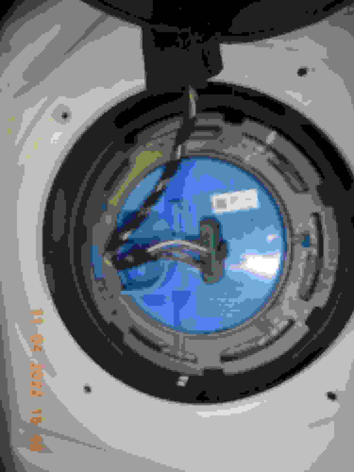
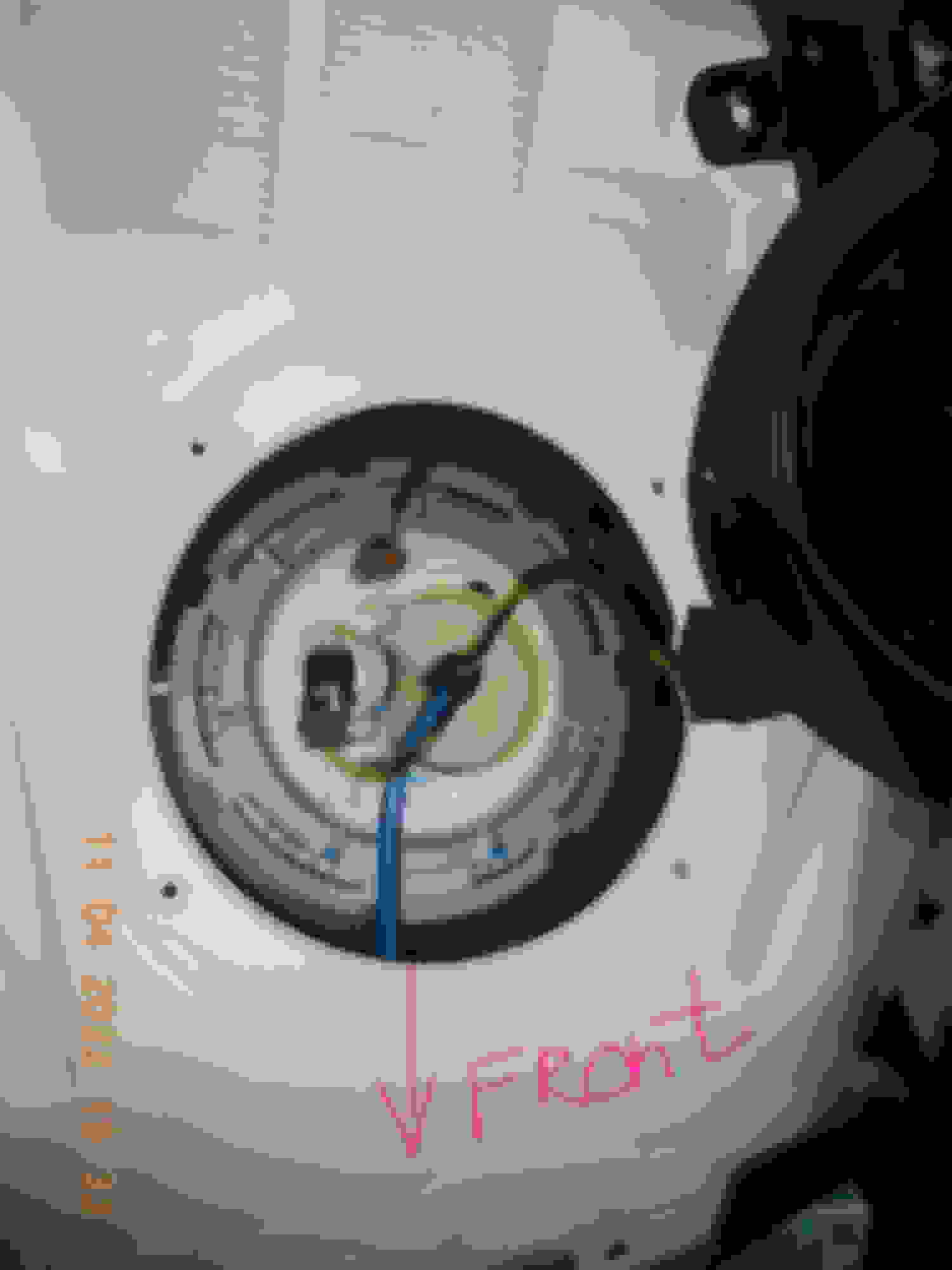
To check yours, all you need is to see the connectors having 6 wires, 2 smaller wires are for Fuel Level. Fuel pump is at the RIGHT rear seat. Fuel filter is at LEFT rear seat.
FUEL PUMP
FUEL PUMP & N118 FUEL PUMP CONTROLLER
FUEL FILTER
My fuel filter is different to E350 W212 I seen on youtube. So do not use my P/N as reference.
NO, I have not replaced my fuel filter yet. I am still trying to log as much data as I can. I bought the fuel filter genuine MB from FCP Euro, coz its cheaper than MB Indonesia by about US$200 even with shipping and 25%ish import duty.
I am in anticipation of needing fuel filter within the next 5,000KM or so, maybe sooner.
I use this estimate for dirt loading of the filter :
I am at 35,000 KM and average I get 7KM per liter or US MPG of 26.46 , hence 5,000 liters is my base line.
For information, the fuel filter size MB uses, it would be best to keep it holding contamination no more than 50-75 grams.
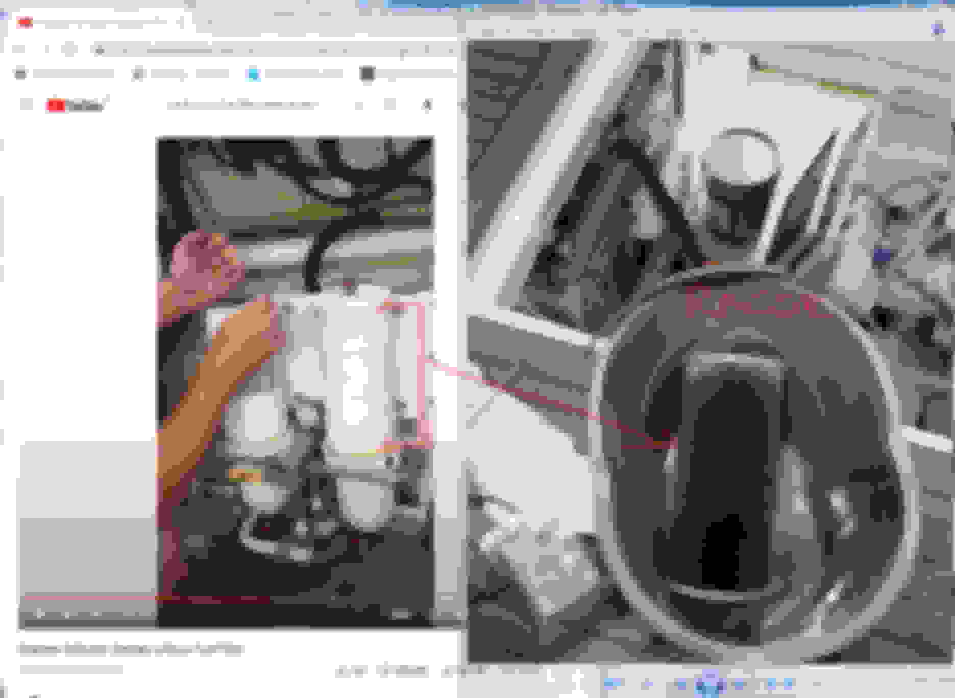
Below is the size of Racor Turbine series biggest filter size, I use on yachts, this is a 500 grams dirt holding capacity allowed, MAX. This is a 24.5cm tall or near 10" and diameter of 11cm / 4.3"
The big Racor above in the pail at right side photo, ( my friend's yacht ) has done only approx 3,000 liters on it.
Diesel fuel in Indonesia has more dirt than 1st world country and any diesel fuel has potential of algae growth if conditions are right. Petrol is much cleaner.
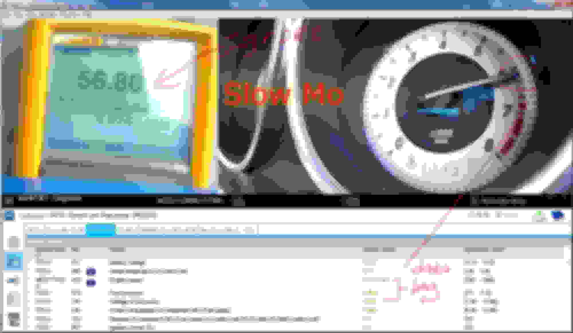
What upset me for now is : this variable speed 3 phase fuel pump of ours, has no Duty Cycle data. The so called VOLTAGE OF FUEL PUMP in red, can not be corelated to a scoped measured duty cycle even.
That VOLTAGE data is kinda useless
AMG car/s has duty cycle and RPM for the low press fuel pump. Stingy SOB MB is.
Perhaps 100% duty is a battery voltage or say 14V ? Well, duty cycle is not that straight forward. Our cooling fan is 10% as OFF and 90% as maximum.
The highest VOLTAGE OF FUEL PUMP I can force my pump to do at WOT 1st gear is 9.6 - 9.8 volts. Below is on the road test drive.
Can I manually actuate fuel pump by Xentry/Scanner...yes, but locked to <6V and approx 5-6 BAR only. I can't even accuratey use manual pressure gauge ( with engine OFF ) to compare properly car's in-tank low press fuel pressure data with mechanical one at engine bay.
ENGINE IS OFF - ONLY XENTRY ACTUATION
ENGINE IS OFF - ONLY XENTRY ACTUATION
ENGINE IS OFF - ONLY XENTRY ACTUATION Virgin new fuel pressure test kit. So me worry for any potential leak, hence so many towel to catch fuel and engine is OFF.
The difference is probably due to the HEAD of small pipe run between fuel tank and engine bay. Its difficult to test when you can't do 100% maximum fuel pump power output. Remember, no fuel flow for engine burn, just a pressurizing event.
Technically given enough pumping time and assuming my mechanical gauge and/or the electric pressure sensor are both accurate... these two reading should be the same at pressurized but no fuel flow
The fuel pump being variable speed/pressure based on N118 fuel computer algo, I can't say with any certainty that slight pressure swing won't happen during my test.
If under real WOT fuel flow, the pressure sensor will show higher BAR/HEAD reading than the engine bay mechanical one, that is from dynamic head of the pipe run and all the bends.
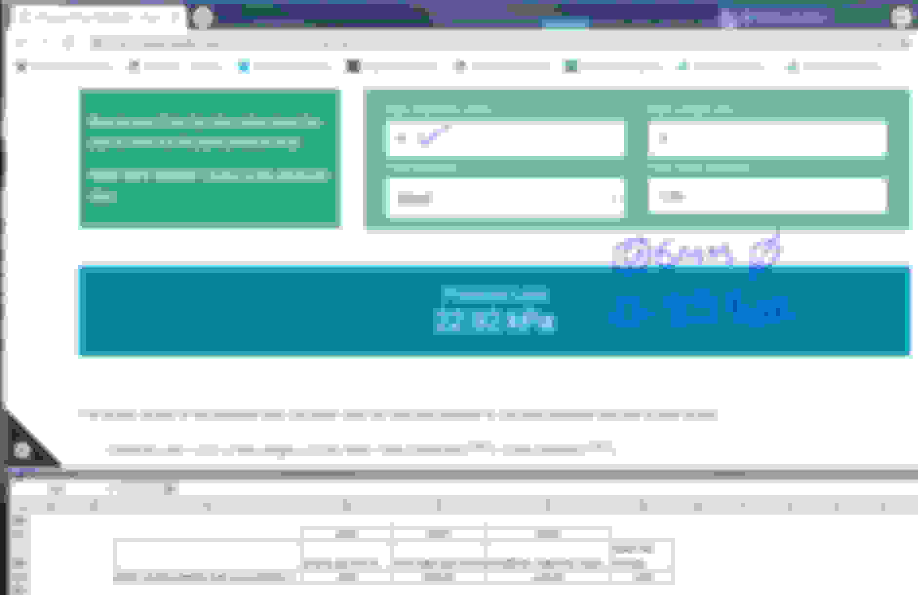
At WOT and estimated BSFC of 350 grams per KW hour there then, per minute fuel burn would be 1.93 liter per minute peak and that would be the flow and HEAD approx would be 0.29 to 0.55 BAR loss to that small long pipe alone,
depending on it is a 5mm or 6mm pipe.
I hope , our pump is a 2.95 Liter Per Minute version as per below.
HEAD LOSS ESTIMATE from fuel filter to HP fuel pump inlet.
Will continue................
Last edited by S-Prihadi; Apr 25, 2022 at 11:32 AM.
Reason: add info
A fuel flow/volume test must be conducted to get proper data.
Pressure alone is not enough for actual system current capability with X% contaminated fuel filter.
Current consumption can be a clue for higher head cause by contamination of the fuel filter element, but I do not have a clean fuel filter amperage draw, of course we must also assume pump is 100% healthy to begin with.
On yacht we use vacuum gauge on the big Racor filter, it is so easy to detect contamination/blockage...so easy and repeatable.
To ADD :
Based on my fuel filter and I am sure the same as in any W212, the pressure sensor is at the output of the filter. This means we can not tell blockage on the fuel pump flow by pressure rise/differential.
A before and after a filter element pressure sensors/gauges can tell with ease on a push a pressure thru a filter set up we have on the car, like how a vacuum gauge would show blockage on a suction based fuel filter to engine set up.
I wish I have a head curve for our fuel pump. I can't find it anywhere.
Our fuel filter element is small
The hoses come with the new fuel filter. So you will need 2 o-rings for the fuel tank to fuel PUMP and fuel FILTER, because changing the fuel filter, the hose end run to the PUMP and you must dig out the hose.
Some older W212 the clear/white hoses has compression clip at the fuel filter itself , mine is glued to the fuel filter and compression quick-clip is at the fuel pump end. Good though, this el-cheapo looking hoses
indeed must be replaced along with fuel filter....better. NOTE : A loose hose to the venturi (suction jet ) can make 1 side of the tank empty.
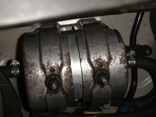
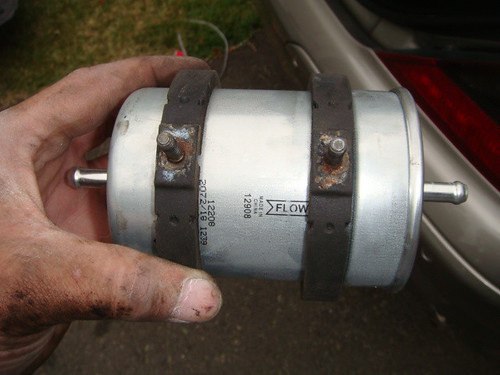
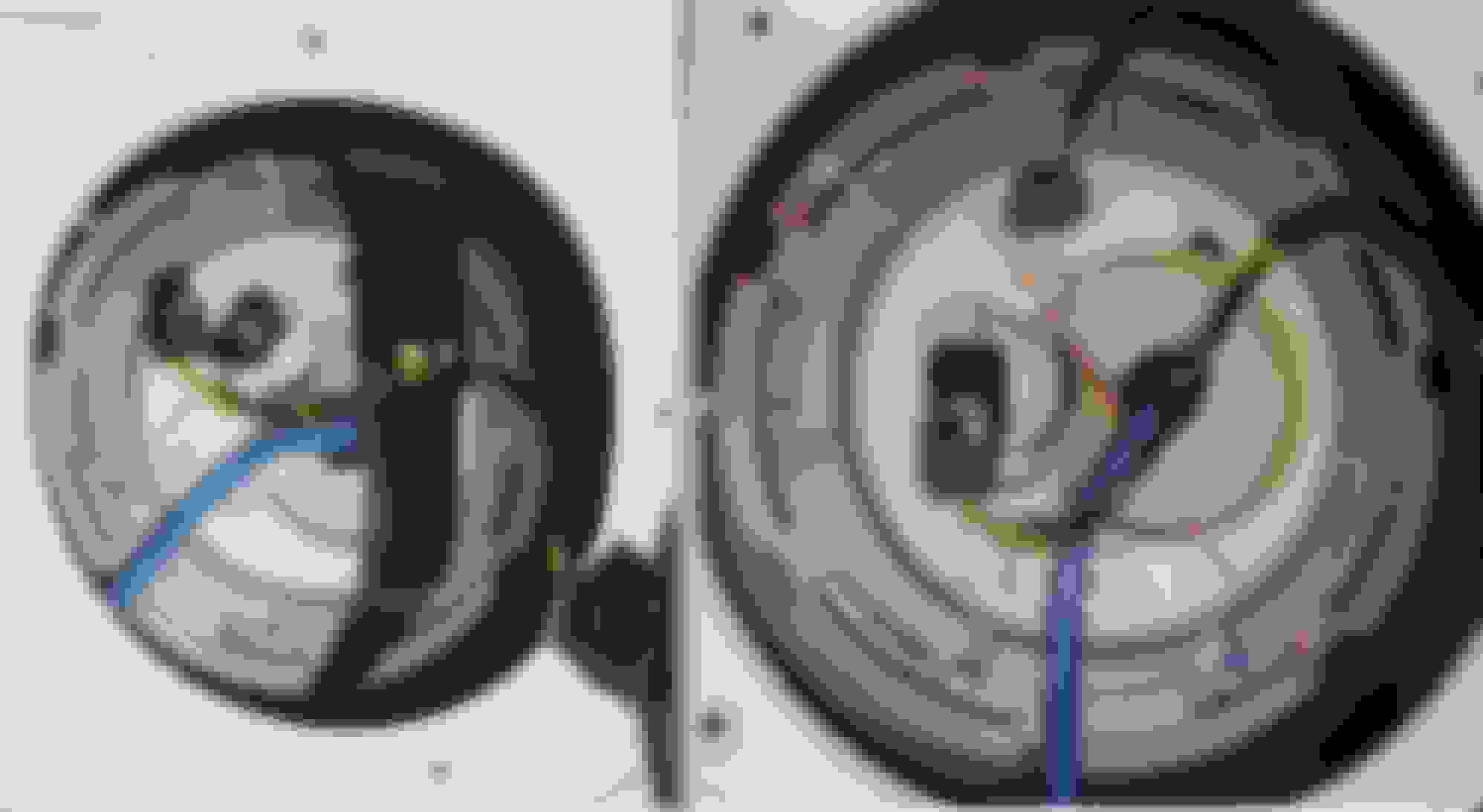
My filter type, ebay image : used one
The middle round shiny metal is something like a REGULATOR, it has spring and produce restriction to fuel filter inlet.
New pressure sensor included too.
I bought from China the locking ring tool.
Landed in 2 weeks , only like US$30 landed !!!....sweet, accurate dimensionally.
I am waiting for someone very knowledgeable on our 3 phase low press fuel pump to chime in please.
I been asking these questions for sometime now.......... 01. Can I test by Xentry actuation a full power/flow of the low-press fuel pump ?
No, the Fuel Pump Actuation Test is probably 50% flow only.
I also can not simply connect +12V to the pump positive feed, this is a 3 phase pump PWM controlled and by only energizing 1 phase, I will burn that phase winding.
02. There is a Drain Fuel Tank actuation from Xentry/scanner, does it make the pump do 100% power ?
I doubt, but neeed to test that to confirm.
03. How about test fuel flow/volume with engine running and bleed it out too via the bleed valve feature of the fuel pressure gauge kit ?
I fear I over bleed and cause fuel starvation to the High Pressure fuel pump.
Our HP fuel pump is a piston/plunger type with extreme fine tolerance between piston and its liner and is doing 7,500 strokes per minute at engine RPM of 5,000 for M276 3.5L and
doing 10,000 strokes for my 3.0 TT engine. M276 3.5L has 3 fuel lobes on the camshaft, mine has 4 fuel lobes.
1 lobe = 1 pumping stroke. A fuel starvation to our HP fuel pump will score the piston/liner and cause overheat too, because the fuel itself is a lubricant and coolant, just like diesel injection pump.
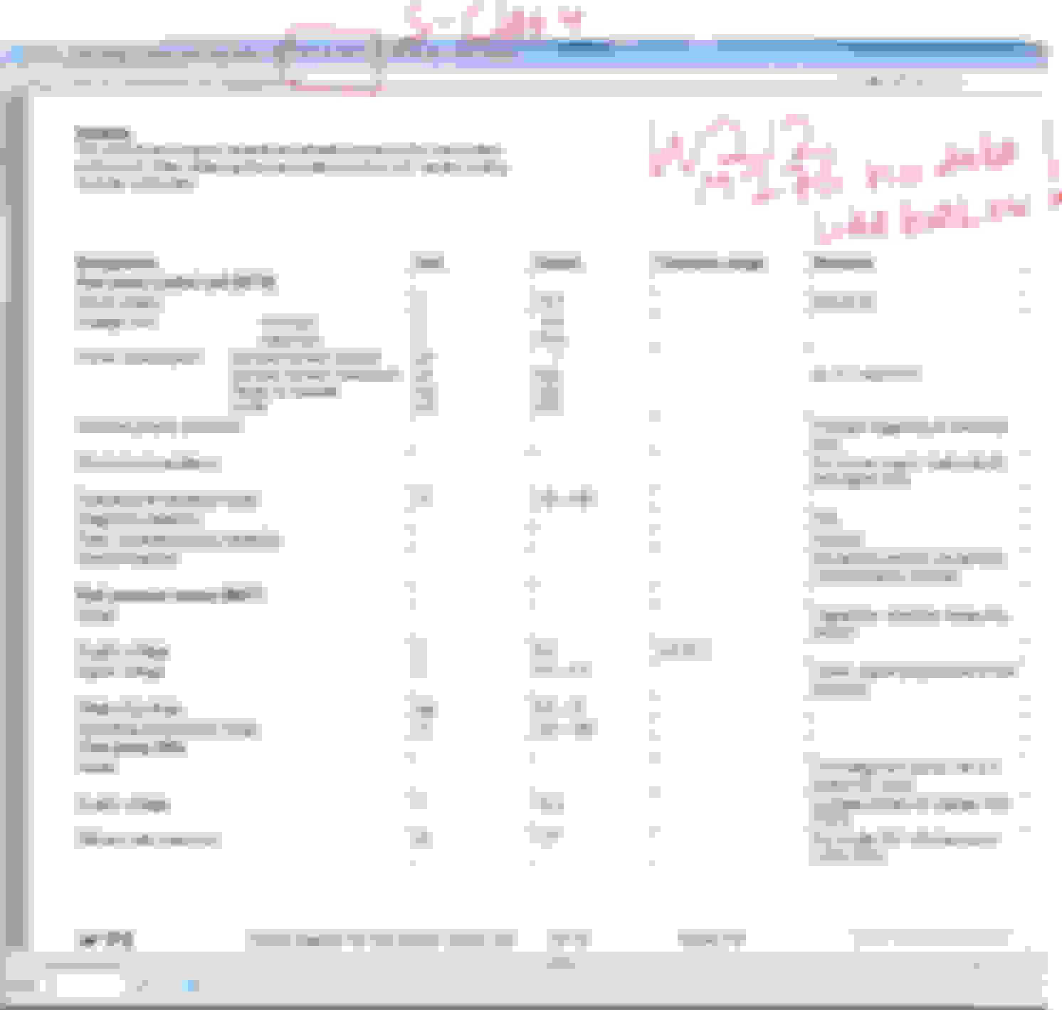
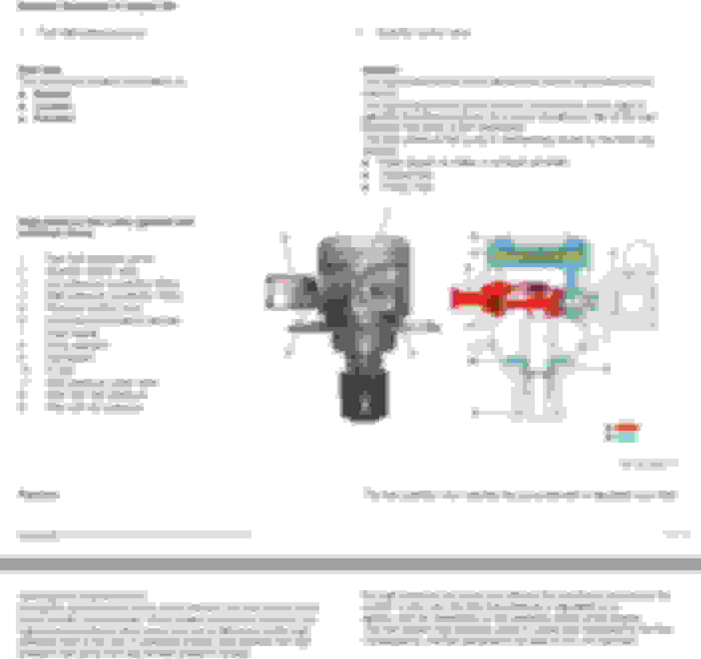
Attached below : the petrol HP fuel pump description from WIS. Item 8 is the piston/plunger.
Damn, how the hell can I test my LP fuel pump at 100% power ????
Without running 100% power on the LP fuel pump, I can never get proper baseline on what is the pump duty cycle ( RPM & amperage/torque ) vs volume pumped ( liters per minute ) vs pressure achieved ( 6 BAR minimum at fuel filter outlet)
===============================
Will continue again soon........ High Pressure Fuel PUMP. This one is another hurt-my-brain item, the : Actuation Angle of Quantity Control Valveoperating parameters found in Xentry/scanner.
I found some new data PID for Low Press fuel pump, the RPM .
However, it is located at the MOST useless location...........at the TANK DRAIN feature. Duugghh
FULL pump power not allowed by N118 fuel computer... as expected.
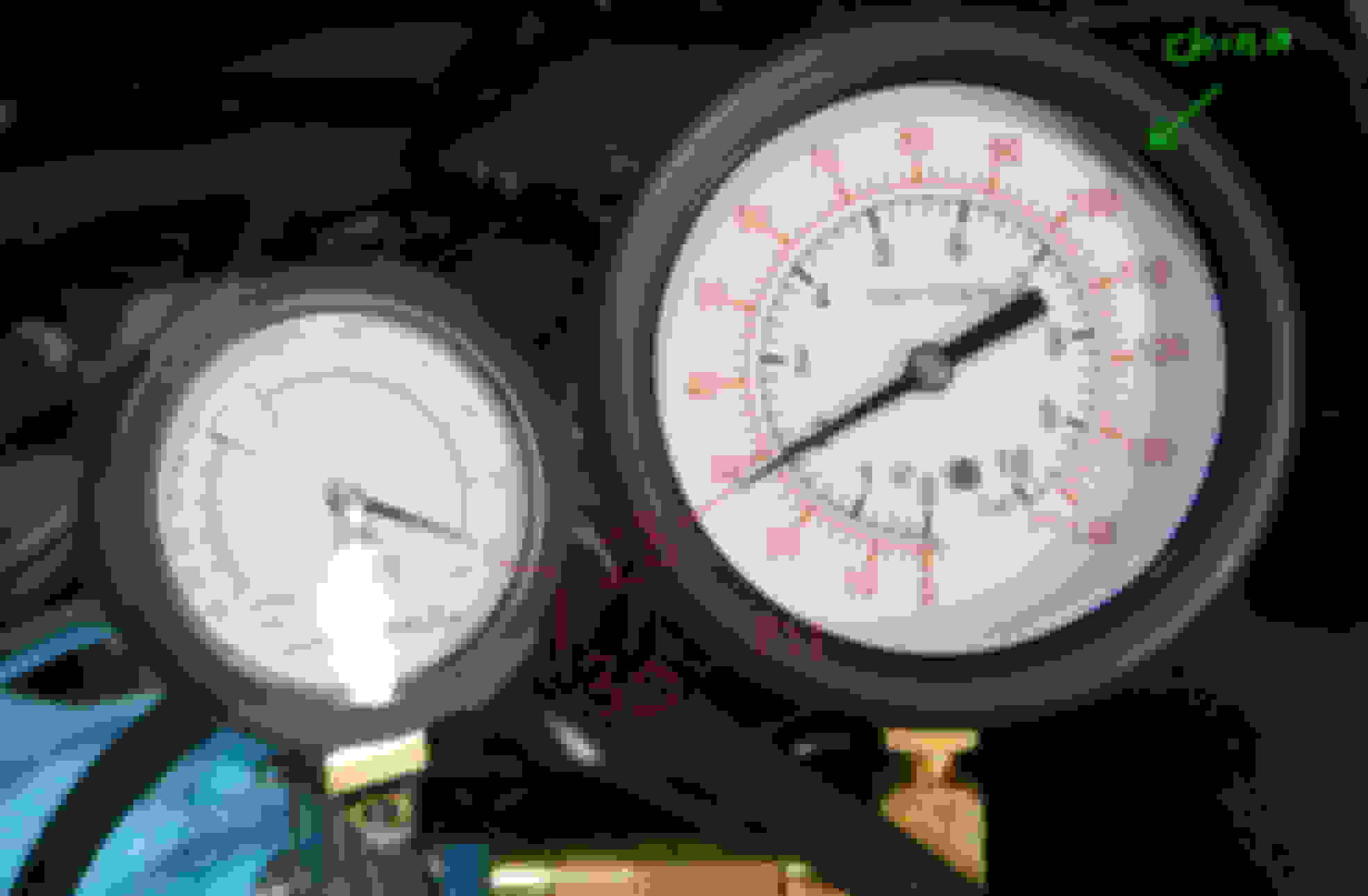
I was also testing my mechanical CHINA MADE fuel pressure gauge accuracy vs the MityVac one, too bad only 30 PSI maximum test.
I will be changing the pressure gauge to my favourite brand, WIKA of Germany. Need to buy reducer adapter first. My Wika is 1/4" NPT and fuel pressure test manifold is bored for 1/8".
This is the second test on the low-press fuel pump ( LPFP ) pressure test.
I need to find out, how the hell I still loose an estimated 0.8 BAR / 11.6 PSI of head on the fuel piping ? That is way too high.
4 BAR of fuel pressure into the HP fuel pump input is too low, according to Bosch that is minimum.
If say my low-press fuel pump can do indeed 8,000 ish RPM, that LPFP is still having much spare capability where the video shown 3,200 RPM at minute 00:31 was hghest allowed by N118 fuel computer
Its really not a good test being stationary, the N118 algo simply wont push LPFP to work out harder than necessary. But me driving my car on the road with fuel pressure gauge attached is a NO NO NO...too dangeorus if leaking.
At the least I get to measure head loss at the fuel delivery pipe from the tank to engine bay.
The fuel pressure tester kit I got is garbage is some ways, local company rebranded it , China made...where else... This one https://www.monotaro.id/s018020045.h...RoCttYQAvD_BwE
Approx US$150 at lowest price store I could find. I was prepared to replace the pressure gauge anyway.
However, I am one fortunate SOB today.
The bloody quick clip lost all its 3 locking ***** , fortunately it was after the engine running test done and I was testing the pressure gauge accuracy.
My finger above is pointing at the Quick Coupler male one.
Below is the Quick Coupler female one.
All good and safe. I was extra cautious anyway since test 1. SAFETY FIRST.
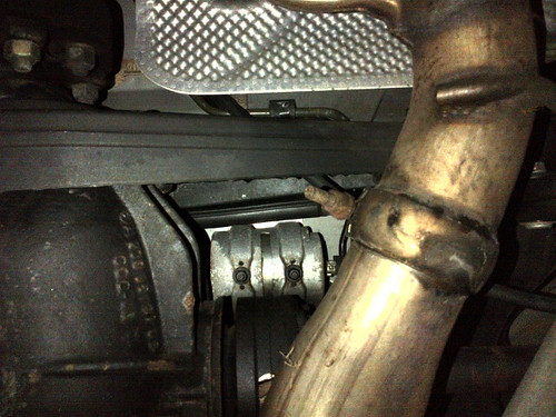
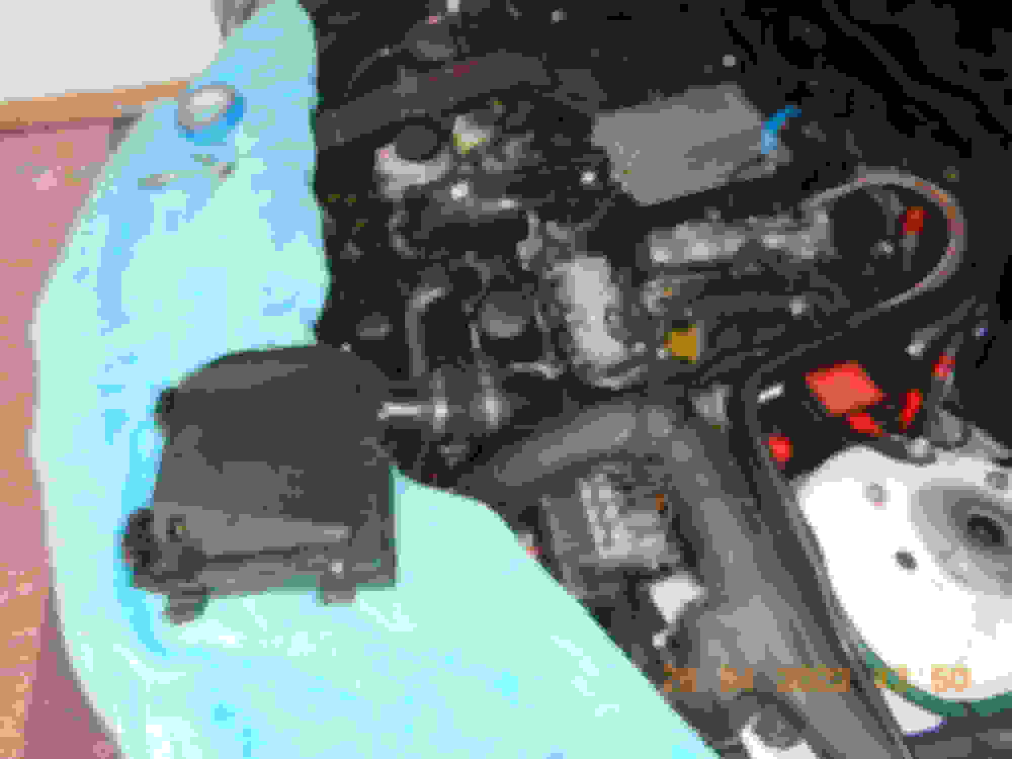
M276 3.0 TT LP fuel test port is at a dangerous location.
Above it, is engine computer's main connectors x 2. Towards left side of the car is 3 COP coils and injectors and fuel will trickle down to the hot turbo.
This is a Vee engine, so fuel leak will also pool in the middle.
M276 3.5L fuel test port is near Bank 1 camshaft sensor ( right side of car ) and is aiming at radiator....much safer locaition if Murphy Law strikes.
I dare not , NOT use the air filter, 1 small stuff drop into turbo = bye bye
Now, fuel pressure test port for those who wants to know.
I can say with high degree of certainty, this is a 1/4" SAE 45* Flare fitting. Some HVAC using R410a uses this 1/4" too so I read. So it is not metric... LOL.
I tested the fitting of the pressure tester on my Robinair vacuum pump and its the same.
FUEL PRESSURE TEST PORT, USE THIS TO DRAIN FUEL FROM TANK TOO
Enough for today. Let me try another Test #3, when WIKA gauge ready to use and me need to sort out the quick coupler issue too..........
I need to track down actual/true head loss between fuel filter outlet to engine bay test port.
While waiting for my low-press fuel pump ( LPFP) tester kit to be fixed, let's discuss the High Pressure Pump ( HP Pump ). It is a Bosch unit.
This HP pump is not a volume delivery pump per se, it is a pressure pumping as its main design. More like a pressure booster or pressure multiplier.
It can not deliver more liter-per-minute than what the LPFP provides it, as simple as that.
The best video animation on it I found so far is this one :
Our HP pump family is this one : https://www.bosch-motorsport.com/con...113098763.html
The fuel pumping capacity probably a bit lower for ours. The link shows 1.1 cm3 or 1 milliliter /cc per rotation of camshaft...meaning per maximum pumping stroke if TDC and BDC of the piston is achieved.
Audi techy has a good information on this HP pump too : start at 16:00
M276 3.5L uses 3 fuel lobes to work this pump. My 3.0 uses 4 fuel lobes. 4 lobes can mean higher pressure or it can also mean more stable pressure per engine revolution , depending on how high the lobes "lift" are.
For our 4 stroke engine, camshaft rotation is 1/2 of crankshaft. So a 5,000 RPM engine , camshaft RPM is 2,500 only.
3 fuel lobes = 3 x 2,500 RPM camshaft = 7,500 pumping events
4 fuel lobes = 4 x 2,500 RPM camshaft = 10,000 pumping events
This is from a 3rd party camshaft maker
M276 3.5L camshaft fuel lobes
3.0 TT camshaft
M278 also uses 4 lobes and has 2 HP pumps.
The HP fuel pump Fuel Quantity Valve/Solenoid is a normally-open design.
If the engine computer does not give power or pump went bad at the Quantity Control Valve, it will stay open and allow a limp home mode using low-press fuel pump pressure of 4-5 BAR to fire the injectors.
All explanation so far sounds simple, but the precision to control the activation of the Quantity Control Valve is a tough one.
Lets use cam's highest lobe protrusion/lift as TDC ( Top Dead Center ) and its lowest lobe as BDC ( Bottom Dead Center ).
By design of check valves & yada yada.... this HP pump can only create pressure if the Quantity Control Valve ( QCV) is energized or CLOSED at the right time.
So pressure is increased by closing HP pump input during a compression stroke of the pump. This means the QCV need to be energized.
Suction volume is achieved by leaving QCV un-energized during downward or suction stroke of the pump.
Suction volume can be reduced, if QCV is energized/closed during a downward or suction stroke of the pump
Remember : The HP fuel pump Fuel Quantity Valve/Solenoid is a normally-open design.
A rough estimate below, in a perfect world
So, where does my frustration comes from ? , when I said in earlier post :
==============
"High Pressure Fuel PUMP. This one is another hurt-my-brain item, the : Actuation Angle of Quantity Control Valveoperating parameters found in Xentry/scanner."
==============
My engine uses the camshaft with a 4 fuel lobes. That means per 90 degrees of the camshaft revolution, 1 complete pumping event aka suction + discharge event occured. 45 degree suction and , 45* pressurizing.
In a 3.5L with 3 fuel lobes, per 120 degrees of the camshaft revolution, 1 complete pumping event aka suction + discharge event occured. So, 60 degree suction and , 60* pressurizing.
In theory, my pump maximum Actuation Angle of Quantity Control Valve for best pressure/output is 45 degrees after BDC towards TDC.
So at 33.5* of Actuation Angle of Quantity Control Valve lets call it simply as ANGLE, it makes sense that I can get 191.9 BAR of fuel pressure because supposedly 33.5* out of 45* is 74.4% of the allowable working angle is utilized.
Now look what happened, 66.6* ANGLE and my fuel pressure down to 150.4 BAR ... hmmm. Dang, all GDI engines I seen, best highest pressure is at highest engine RPM...
Okey, 66.6* , let use 65* for easy sake. 65 minus 45 = 20 degrees of ANGLE, which is LIMITING the flow/pressure of my fuel pump to hit 200 BAR.
I meant to say : that there is 20 degrees during SUCTION which is on purpose not being utilized..... while full 45 degrees of compression did take place. This is my assumption.
Knowing by estimate that my engine at highest burn rate is only 1.93 liter per minute, the HP pump in a perfect world ( before efficiency loss yada yada ) at 4,000 engine RPM can pump out 6.4 liters per minute.
So, again I am assuming......... that the engine computer must balance between volumetric and pressure and has to CUT off fuel supply at higher RPM by closing that 20 degrees of SUCTION period.
So I asked these questions :
01. Is my engine actually a 150 BAR GDI pressure or what ? I thought it is a close to a 200 BAR category.
02. Why at such high engine RPM, a beautiful high pressure of 191 BAR which can atomize the fuel better.....not being utilized to the fullest ...and 150BAR was choosen instead ?
03. Is my HP Pump fuel quantity valve is off the timing ?
Now, can I scope my camshaft angle vs duration of activation/energize state of the Fuel Quantity Valve ?...yes I can.
BUT..... BUT, I do not know where at the camshaft angle is the actual position of the 4 of the TDC aka lobes highest lift exactly , I need that ZERO as starting point. 1 TDC point is enough.
TOTAL Actuation Angle of Quantity Control Valve Is MB speaking of Camshaft angle or Crankshaft angle.... what make sense is camshaft angle. Let's use that.
Scanner/Xentry said 30.9 degree of actuation angle at idle in my garage. Not on the road.
I measured 40 camshaft degree worth of QCV being energized. Is the 40* all at SUCTION period ? I don't know , I do not have the ZERO or the TDC position
See below, 4 period of QCV activations per 1 full revolution of the campshaft.
NOTE for below scope capture. I on purpose is using 360 degrees for 2 revolution of the engine, so that the degree ruler works for CAMSHAFT actual revolution. If for cam to crank correlation check, that would be a 720 degrees ruler.
What I read from Bosch HP Pump patent, yes patent.... that short PWM signal at the right side of my measuring ruler ( 290 ms region) , that is noise reduction for the piston , like electromagnetic braking.
If you enjoy headache, I am attaching the patent
So where is the cam's 4 of its TDC ? I don't know exactly , I can guess but it would be like 10-15 degrees OFF.
I kept trying hard to find the correlation as per Xentry stated ACTUATION ANGLE , but it does not match my measurement on the Pico scope.
I am not suprised Xentry is and can be like a generic data display for MB cars say now to the last 20 years, where its data content can be misleading.
Case to point out is the duty cycle of the boost controller valve of my turbo. Xentry data is wrong for my engine and maybe correct for older cars.
I tried finding where the cam's TDC is, also not possible as the degree or duration of the Fuel Quantity Valve being energized can spread left or to the right of the blue marker arrow I made, all depending on RPM and
I only have stationary scope data, not a test drive real WOT run. Different engine load mode will have different operational strategy of this fuel quantity valve, I am sure.
The frustating part of Xentry is the lack of COMMANDED data parameters.
This data is the value that ECM demands a device to perform to and ACTUAL is what the device can deliver.
In Audi/VW ( pobably BMW too ) , there is a COMMANDED fuel rail high pressure and ACTUAL/ACHIEVED one, so it is easy to see performance going downhill before any DTC can be triggered. Xentry only has the ACTUAL pressure.
This is one example only. There so many more pleasantly helpful data I seen coming out of Audi/VW diagnostic on youtube channels of techy repairing these brands.
Why MB is so stingy with COMMANDED data parameters ? I don't know.
The more data we have, the faster troubleshooting can be done.
However, from an owner's long term ownership experience.... we are quite blind as-is now and need to log our cars when all system are still healthy.....if you want to be able to do predictive maintenance and not a REPAIR caused by
limp mode or very bad-very low performing components setting critical DTC.
Here is something confusing in the effort to learn more of the Fuel Quantity Valve. I forgot to share earlier, sorry.
The scope/laptop is sync by video to the scanner in real time, the scope displaying data is probably lagging to scanner data by 1 second at the most upon rev up or rev down.
Pay attention when channel B red, the activation of the Fuel Quantity Valve was not performed by engine computer ( channel B zero data ), but scanner is still showing actuation angle of 30.3 degrees
Minute 00:06 and 00:13
Surya, thank you for showing our fancy fuel pressure regulation by Bosch.
ECU measures and controls the fuel pressure of both low and high pressure pumps. One pump is mechanical the other is electrical, both are regulated.
delivery rate depends on rpm
I was wondering if the pressure is kept flat across engine rpm -or if it does varies significantly ?
I am kinda guessing...
> Both Lo/Hi pressure pump regulation controls are used to maintain a fixed pressure regardless of all variables (demand, Rpm, voltage, temp) such that idle pressure nearly equals to redline pressure, right?
Last edited by CaliBenzDriver; Apr 27, 2022 at 09:05 PM.
Cali ask :
I was wondering if the pressure is kept flat across engine rpm -or if it does varies significantly ?
There is a Pressure vs RPM vs Load table/Map programmed in the ECM.
NOTE : At idle, 120BAR is the typical pressure.
This is the high-press fuel rail pressure activity/algo the engine computer been programmed to do. My engine is healthy, so this ACTUAL pressure should be correct.
Yes, I am pissed that there is no COMMANDED/TARGET fuel rail pressure data to compare it to.
Absolute throttle ( throttle body ): 85 degrees is maximum opening angle
The designated 150 BAR max pressure at WOT or near WOT seems to be based on my throttle body opening angle ( my foot on accelerator ) and is not RPM only.
Below is a per 1 second data PID , part of above graph
Below is an example of me hesitating to kick down not WOT yet just partial, the throttle body opening angle shows and its obvious, the engine computer is using throttle angle more for fuel rail pressure control than RPM.
The mild de-acceleration phase ( DECEL) is a good pressure vs throttle data to see. I was down from 153 to 136 KM/H and RPM heading down from 4,700ish to 3,978 as throttle opening was 16 - 15 ish degree only
This is from BMW B58 ( 2015 ), from a NOX sensors shop. B58 uses the same Bosch HP pump family as our E class M276 V6 N/A or Turbo and M278 V8. https://bimmerprofs.com/b58-fuel-system/
The writer who is used to see duty cycle % to the Fuel Quantity Control Valve as a value of HP pump work/energized , got a bit suprise that
the duty cycle is no more relevant for the new HP pump... LOL....because it is the now MB equivalent of Actuation Angle which matters for this HP pump design.
However, since he has COMMANDED fuel rail pressure vs ACTUAL, that is all that matter.
Same NOX company. Discussing BMW HP fuel pump pressure management. Up to N55 BMW, it is still using older 3 pistons pumps, but working concept is the same. https://bimmerprofs.com/hpfp-pressure/
This is how the B58 fuel rail pressure control algo and mechanical performance works :
94% of throttle opening is like 83 degrees on my engine, near MAX. Actually I like % better than angular for throttle body. 2,889 RPM pedal to metal WOT, fuel pressure is 194 BAR. Nice
At 3,966 RPM, 75% throttle angle or 85x75% = 64 degree on mine, the fuel pressure is still 182.5 BAR ...very nice.
The older BMW N55 engine ( 2009 ) fuel pressure table
This is AMG M177 engine the hot Vee , surely a performance oriented fuel mapping.
From Taso's utube channel
starts at 04:33 to 06:43 , also notice his understanding of the ACTUATION ANGLE and must be for AMG engine/s being 125 degrees as maximum... now I know its not the case for my engine for now untill really proven otherwise.
So I guess AMG fuel mapping is Fast & Furious and my engine fuel mapping is "Old Man Map,Hence I get Furious"
If I somehow that my fuel filter dirt level is limiting fuel flow but not to the level worthy of DTC, and ECM play safe setting 150BAR as max pressure under high load,
we can see soon when I replace the fuel filter. The abudance of HP Pump reserve capability ( calculated ), does not make sense to not use 190 BAR all the way to redline.
I know why this stuff drives you mad, it looks very counter intutive ! Everything we thought was true is put on its head with this crazy computers:
Fuel rail vs. TPS.
It looks like ECU is taking away pressure when you give it throttle. Normally you'd expect the opposite: either flat or richer during accelerations... hard to make sense of decreasing pressure.
It means the injectors must be able to compensate for pressure decrease instantly - Then what about pressure increase, same thing: injectors can make the difference seemless!
So why bother not to keep the pressure constant like a good old 12V pump with diaphragm & spring regulator, one single pressure.
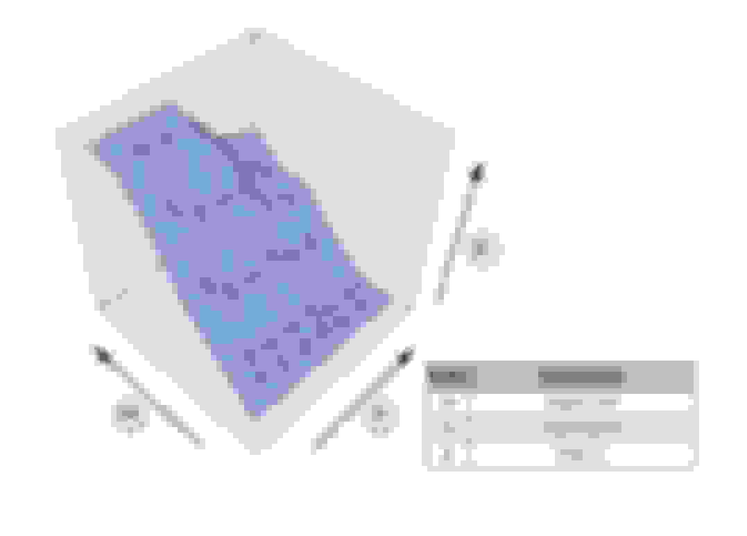
Nice 3D fuel map
I can see how ECU is bringing more fuel to the rail during higher load. We observe how pressure is regulated to stay flat against camshaft Rpm that increases the pump output.
Taso's pressure chart.
Even Master Tasos has a hard time pining down the pressure control of his rail.
He is showing pressure vs. angle valve vs. Rpm.
- Further down, we'll see that it should be either load or lambda/STFT.
- Tasos says fuel rail pressure is increased based on Lambda feedback.
ECU uses pressure to help lean out injector's work and enrich a lean burns.... I thought injectors timing could control mixture with far better granularity.
- He mentions upgrading the LP pump but not the HP. something about starvation... but LP not regulated for max output. I guess LPFP_controller keeps output around target pressure.
At any rate it's interesting, so thank you for leading us down that path.
> Reverse engineering software:
I know you're interested about forecasting your fuel filter getting plugged by contaminants...
I think we have a way to understand what the developers were after with this regulation.
-- Look at the fault settings criterias for the Fuel Pumps.
-- LPFP controller certainly packs less codes than the busy ECU, easier to parse through DTC criteria of LPGP Module.
-- This will lead you to understand what threshold conditions trigger a "low pressure" flags.
Hope this helps,
Last edited by CaliBenzDriver; Apr 28, 2022 at 08:37 PM.
Cali wrote : > Reverse engineering software:
I know you're interested about forecasting your fuel filter getting plugged by contaminants...
I think we have a way to understand what the developers were after with this regulation.
-- Look at the fault settings criterias for the Fuel Pumps.
-- LPFP controller certainly packs less codes than the busy ECU, easier to parse through DTC criteria of LPGP Module.
-- This will lead you to understand what threshold conditions trigger a "low pressure" flags.
Hope this helps,
=====
I read the available DTC from N118 fuel pump controller list.
The P008A00 MB is the only describing fuel at low pressure DTC. The rest of the DTC is about electrical problem at the fuel pump and pressure sensor and Fuel Quality sensor if the car has such option.
Knowing low press sensor position is after filter output and it lost minimum 0.5BAR of pressure/head at the HP Pump inlet port from the small delivery pipe fuel tank to engine bay,
I bet before even hitting 2.5 BAR which net value to HP pump is estimated at 2.0 BAR only ........ we will get DTC from the high pressure side of the system. P008700 from ECM would pop out earlier than the P008A00.
Too bad P008700 does not specify how LOW is a LOW ... 24 BAR less than what low BAR/pressure specified ? I think only the engineer himself and his mistressknows what is the specified fuel rail pressure
This is the problem with generic codes. GDI fuel pressure Gen 1 and current latest Gen been going up. MB should create more custom DTC P0087xx specific to each engine, if they want to be super ****.
I doubt they want to do so.
Diesel-Gate VW always provide SPECIFIED/COMMANDED fuel rail pressure
I think another factor to consider is the level of azz-hole-ness of the engineer setting the trigger limits.
For marketing sake in the name of creating an impression the car is very reliable/durable, an engineer can push the DTC trigger level as low/tolerant as possible close to a bad-driveability and then trigger a DTC.
Doing so may extend DTC arrival a few 10 of thousands of kilometers more of use for regular light footed-on-the-throttle John Doe.
Same with LifeTime Tranny Oil marketing philosophy bull-now-shi-et-later . LifeTime of the 3 - 5 Years Warranty Life that is. ha ha ha.
I am going this Fuel Filter Prediction path because I can feel my engine brute-ness 2nd and 3rd gear pull is reduced since the last few thousands KM ago.
I don't time my 1/4 mile thingy...I way passed those desire , I use by butt dyno more .... LOL
2nd and 3rd gear is the longest WOT pull I can create for max fuel flow demand. It would be nice if I have autobann and 4th gear WOT pull is even better.
Hence data for LP pump & existing supposedly mild-clogging fuel filter at maximum 100% flow is a valueable benchmark. Next chance is 7 more years ... if I keep the car that long passed its 10th Bday.
You know, in my yacht maintenance days, fuel filter clogging/cleanliness is Numero Uno concern.
Our diesel fuel is bad quality and dirty. Our fuel tank is so big and hence alot of air space for moisture to collect.
Our diesel fuel is cooled by seawater heat exchanger on its return path to the fuel tank, hence big temperature difference will trigger sooner dew point temperature producing water vapor in a country with 85% humidity.
We have vacuum gauge to monitor fuel contamination build up. Our king-kong sized primary filter the twin Racor FG1000 per engine , is a 10 micron element . I use a 0 micron, other people/yachts use a 30 micron .
The engine's own secondary fuel filter is also 10 micron. This is a 200 BAR oldie diesel and not common rail which will have 2 micron fuel filter on engine (secondary).
Any filter has what is called beta ratio as an indicator how good it will be at trapping claimed contamination size, in my case 10 micron rated element. https://www.machinerylubrication.com...ter-efficiency
The Racor 1000 series element I use is said to be approx 85% ish beta ratio by those who have measured it. Beta ratio info is not easy to get.
So, one day I was sailing home from a 125 n.miles away dive location and we cruised at 31 knots. We burn 275 Liters Per hour or 72.7 US GPH at 2,100 RPM on this V-10 820HP x 2 MAN diesel of 1995 if at 31 knots.
US MPG on this 53 sportfishing yacht in car term is ( 31 * 1.15 ) / 72.7 = 0.49 MPG and is already a good fuel economy for the 29 tons weight of the yacht and that very respectable 31 knots cruise speed.
The beauty of big enough yachts with total 1,200+ HP is , we learnt a lot about fuel filter 101 because we use so much fuel per weekend trip and we are always 80% of WOT on fast cruise.
So I day and this happened only once in my 8 years taking care of the yacht, the fuel supply had very small sized contaminants lower than 10 micron.
How I know is, it is my habit when we are close to home base marina, and already light on fuel load ( 860 gallons / 3,250 liters fuel left over to about 1,000 liters / 165 US Gallons )..........
we do 100% WOT for 3 minutes to check all system max load integrity and that means 2,100 RPM raised to 2,300 RPM the maximum RPM.
The engines could not made it pass 2,225 RPM and I knew the primary fuel filter on the engine is choking, albeit vacuum on the big Racor filters was still within good number.
So later I removed the twin canister fuel filter on the MAN engine and cut it open, indeed very fine contamination in its paper elements.
The fuel filter change protocol on this yacht is : every twice on the big 2 x dual Racors, once for engine's twin fuel filter and this is about per 5,000 liters / 1,323 US Gallons and vacuum rise approx 10 inch Hg ( or 4.9 psi negative ) at the Racor.
Back then 1997 to 2005 our diesel fuel was TOTAL garbage.
Ability to load marine diesel engine for hours on end at 100% if you so wish is so easy, no traffic jam , no speed limit in open sea and 30 statue mile is considered quite a distance already.
Propeller to engine load is a fix 80% at light liquid* ( *1/3 fuel and water ) & passenger load on the yacht, on a flat calm sea and all underwater system clean of any fouling.
To create similar fuel burn load on a car, we can use a wheel hub hydraulic dyno with programmable load. There then, any minor restriction will show by the 1st 60 seconds of non stop WOT.
So much good memory and learning on that yacht, I bought her ( for my friend ) from a broker in Florida back in 1997 when she was only 2 years old.
I spent 1,500 engine hours on her and near half a million liters of diesel I have burnt on her engines. 412K liters / 109K US gallons approx.
Some entertainment Cali : The highest fuel burn engines combo I ever tested for a client, it was in 2014 in Italy.
1,543 liters per hour / 408 US GPH. 120 footer sport yacht. 2,400 HP x 3. MTU 16V2000 M83 driving KaMeWa waterjet
We get to the same conclusion that scheduled preventive maintenance is better than troubleshooting degraded performances.
You've shown how the fuel pressure regulation is influenced by multiple factors. Getting a valid baseline pressure during a WOT max demand may be adventurous.
Reverse engineering the low pressure fault criterias only cover extreme cases. You are interested about optimal performance, not spotting a 100% plugged filter.
A scheduled tank cleaning plus a new filter sounds like the best way to go. Do you think the water condensating out of tropical humidity air is what causes most of the contaminants. Is tank cleaning essential to preserve the new filter from a short service ?
Do you think there's any way to retrofit FOILS on those 0.5MPG yatchs?
I've seen large commuter vessels on the HK-Macao route, mounted on 4 skis with turbo-jet engines to reach top speeds... pretty zippy ~40mph !
Last edited by CaliBenzDriver; Apr 29, 2022 at 04:04 PM.
The quality of underground tank cleanliness of fuel station in Indonesia which are government (state oil company ) owned, well not so good. Getting better and better though, so thats where contamination is from usually.
They were the only one with 98RON ( European RON ) fuel grade till some months ago when Shell got V-Power Nitro+ 98 RON too.
My car fuel tank label is 95RON, but I must have more than 95, so when processing quality drop, I have 3 RON back up. Anyhow now the RON is 92 or 98, no more 95 for many years now.
I don't really trust a 100% anything state owned in terms of consistent quality service or product 365 days a year.
Some fuel station under goverment brand is privately owned, like a franchise. The one in one of the marina is such a case and their meter is over-reporting by 10%. They steal 10%, which is not uncommon for private owned state brand fuel station franchise.
FOILS is not for yachts, the yacht draft become so deep and its troublesome in the marina. In really bad sea, FOILS is not good.
=============
A scheduled tank cleaning plus a new filter sounds like the best way to go. Do you think the water condensating out of tropical humidity air is what causes most of the contaminants. Is tank cleaning essential to preserve the new filter from a short service ?
Condensation is bad thing in fuel tank but super low quantity water is no big deal as petrol can not developed algae like diesel fuel can.
I will know how dirty/clean my tank is when I change the filter. I will surely update.
You know, I am tempted to "cheat" the low-press fuel pressure sensor to make N118 fuel computer or engine computer N3/10 read lower pressure than actual, assuming I can do it easy and safely with resistor.
Just curious what will happen to the command for speeding up the motor ...or what decision N118 or N3/10 will take.
Is the LPFP speed based on a prepared look-up TABLE ( LUT) ? or it is completely dynamic ? Or a base TABLE + dynamic-fine tuning.
According to MB document, it claimed engine computer over CAN will instruct what fuel pressure to provide.
So N118 must raise or reduce the pump motor speed to achieve commanded pressure, without a basic look up table assist and instead a dynamic-fine tuning 100% pressure based,
I think it will be too slow to respond.
A car engine fuel trim is kinda fix + dynamic.
The Long Term is the kinda FIX value for a set period of time and the short term is the dynamic one while knowing the Long Term is already a compensation factor.
......................
Today I took my car out for its weekly drive, missed it last week... and while at it, log the low press fuel pump RPM.
As usual, it is not possible to get a clean WOT pull 1st and 2nd gear due to traffic.
Where I got the chance to do full WOT 3rd gear pull... but from 5,000 RPM only and not lower, the 2nd gear was not a true full pull too.... ha ha ha...too much cars on the paid highway.
I do not think our 3 phase brushless pump can spin higher than 7,500 RPM.
If I use the 1 Volt = 520 RPM , 13.6V will only give 7,072 RPM
There is easy 0.5V drop at N118 input from a 14.1V alternator, hence I use 13.6V as max.
Sure the Xentry data display lags abit over the instrument cluster RPM gauge, but 511 - 561 RPM per 1 volt seems logical , seeing the actual result.
That M177 engine - E63S
M177 is still a 200 BAR maximum system. Not any higher than ours. What a solid low pressure side it has.
Something interesting I found out today.It is about road resonance/noise and not pump thingy.
My rear set is still not installed yet. But I do have the sound mat/rug there.
If you guys watch the video , 01:52 to 01:59 , that is ending of 3rd gear into 4th, and 01:57 at 4,700RPM ish is 4th gear at about 100 MPH.
If you use a decent speaker with good bass and set volume loud, you can hear the rumbling/resonance noise which I think it is wind + road noise having an orgy
Yes, the car has higher noise with the rear seat off, but I never expected at 100 MPH it is that loud and with that unique resonance/rumble sound only for a few MPH of the 100
or 4,500 - 4,600 RPM 4th gear.
The audio recording is from a GoPro Session and the laptop mic, so bad quality audio and in real life it is so obvious...it feels like my last experience with bad/failed road force variation tire
and plus the additional noise bonus.
I think the fuel tank to car undercarriage region is a good candidate for noise treatment from wind force.
If the front grille of facelift has that 120KM/H whistling noise TSB, perhaps this one is the gurgling noise of the fuel tank to undercarriage.... LOL.
I really like the way your thinking to cheat on fuel pressures. Adding a divider bridge on the sensor output sounds like a nice & easy way
Replacing the LPFP Controller with AMG or reprogramming pressure bias using a used second spare module.... may be too difficult.
I looked at your spreadsheets and video, it's kind of odd how Xentry is still showing us legacy pump Voltage and Amperage values.
Our hightech controller is ramping the pump AC Frequency. This drives up/down the Rpm to match a target Pressure. DC Voltage is irrelevant here.
You can really overlook the frequency to simplify the pump work to track "Pump Rpm vs. Pressure".
Thing is... if you boost your LPFP output pressure, don't you think the ECU high pressure control will make up for it ??
> Learned fuel pressure map:
When comparing the module circuits, I think only the ECU has enough calculation power to run the software that learns new map pressure. I bet these values are handed down to LPFP module through CAN-C. The smart ECU code is maintained centrally and uses the LPFP controller as a satellite to do the heavy lifting.
The rail high pressure is directly controlled by the ECU for real-time response, nearly as fast as injectors.
> Cheating fuel Mgt:
I bet it's hard to cheat world-class cheaters like Bosch
You'd need insider knowledge of how things work down to the detail. Perhaps you can find a whitepaper about fuel pressure control in WIS library ?
I think I overheard Master Taso say he uses "a different pump to prevent starving high pressure pumps" - Note: that's for larger engine size with dual HPFP, meaning 3.0L may already have a good match for single HPFP , right??
Last edited by CaliBenzDriver; May 3, 2022 at 11:35 AM.
Sorry to burst everyone’s bubble here but all this conversation on fuel delivery and the ‘Mercedes’ concept of fuel delivery is riveting reading but a waste of time at best.
The 3 wire pump is not controlled by voltage. It is a variable frequency drive (VFD). It is a 3 phase servo system (same as a 3 phase motor). The voltage is constant, speed is controlled by the frequency on the 3 phases, with power measured by the current on the 3 legs. This is the same drive concept used in all robots, automation servos, positioning concepts….
The 2 wire system is a pulse width modulated (PWM) system. This is a DC rare earth motor functioning as a servo drive. Voltage is constant, speed is controlled by the on/off state of DC, power is root mean square (RMS) of the current (like AC RMS with a PWM understanding).
All the research in these posts does not apply to our cars.
The Mercedes concept of delivering fuel to our engines is STUPID and that is a generous statement.
I think it wise to establish creds…I’m a senior staff electrical engineer at Cummins.
A fuel pump in the trunk with the fuel filter 3 inches away from pump and a regulator 3 inches away from the filter then send the fuel on a 15 foot trip to the engine with 5/16 fuel line is insane …YA…the Mercedes brain trust.
My fuel pump controller gave up via fluctuating pressure and triac saturation. I looked at the system and lost lunch...so...
� Removed controller
� Removed pump pressure sensor
� Removed regulator
� Wired pump directly to power from car
� Ran 3/8 fuel line from filter output port to engine (remove effect of laminar flow)
� Installed 100 psi max fuel regulator at fuel rail
� Attached existing 5/16 fuel line to waste port on regulator (OK for waste line (laminar flow effects low)
� Attached regulated port to fuel rail
� Attached 5/16 fuel line at rear to fuel tank port of old regulator
� Dialed in regulator to 72.5 PSI
� Done
Car starts in less than a second and when the Super Charger kicks at WOT, the fuel pressure varies NOT...I mean NOT...idle or WOT...NOT.
Same concept used when I converted my 1955 Thunderbird 292 to fuel injection.
I'm not smart here folks, it's how it's done, refer to any Holly aftermarket system. If any disbelief, call Holly Engineering for guidance.
The above system was a PWM system.
The ECU takes care of all fuel delivery control.
The fuel map no long has to accommodations for varying fuel pressure.
Not a light on the dash or a bang in ECU calculations.
SL launches like a bottle rocket all the way to 155 MPH than calms down to the smoothest idle.
Just do it.
======================
My fuel pump controller gave up via fluctuating pressure and triac saturation. I looked at the system and lost lunch...so...
� Removed controller
� Removed pump pressure sensor
� Removed regulator
� Wired pump directly to power from car
Awesome information, your 2007 SL55 still the regular 2 wire fuel pump motor I believe.
How do you propose to do the same on a 3 phase newer fuel pump ?
Use a 3 phase ESC and set near max duty cycle and let the pressure regulator do the rest ?
Your 2007 N118 fuel controller for 2 wire motor may not have fuel parameter watch dog like newer N118 for 3 phase fuel pump.
I bet the moment we 3 phase pump owner remove the N118, loosing the N118 CAN Bus communication , the engine computer will trigger a DTC and do its whatever reaction the software engineer designed the ECM to respond to when loosing N118.
The 3 phase system is great.
The pressure is controlled by the ECU via a pressure sensor near the fuel rail (input device) where the pressure is utilized...not in the trunk.
There is no return-to-tank fuel line
The pump requires less cooling via fuel flowing through it (output controlled by need)
Pressure at pump is static for the most part
Shortcoming of system is laminar flow (fuel feed to fuel rail)
Install 3/8 or larger supply line to generate turbulent flow
Pressure at fuel pump outlet will be near equal at fuel rail
Throttle response and WOT will have the fuel pressure the ECU is expecting (no recalculating the fuel map)
The 3 phase system is excellent...should have been employed years ago.
Kick your feed line size...good to go.
It's all about fuel line size.
I would like to have the inverter style system however my short sighted engine could care less...it just want fuel at a regulated rate.
Yank,
I think you best take a look at W212 E350, M276 200 BAR / 3,000psi GDI fuel system first hand.
I believe your 2007 SL55 engine is an M113 and that is a low pressure fuel injection system...correct ?
In this thread we are discussing a direct injection system where the sensor at the fuel rail is a high pressure sensor ( with temperature ) and it is the one managing pressure
for the fuel quantity valve of the Bosch High Pressure pump, it is not for the low fuel pressure pump at the fuel tank.
Yank wrote :
The pressure is controlled by the ECU via a pressure sensor near the fuel rail (input device) where the pressure is utilized...not in the trunk.
Your non GDI fuel injection system of M113 only need 1 fuel pressure sensor because there is no pressure boost needed, there is no HP pump. Your engine only requires <70 psi probably.
You are describing your fuel injection system, not a GDI
If you are from Cummins diesel, think of M276 as oldie 80s Cummins 6BT engine with the rotary injection pump, but no mechanical fuel lift pump and instead electric fuel pump from fuel tank.
I agree on using bigger fuel pipe for less pressure loss, but the fuel filter output port is small ,,,,
There is no customization of the control to a VFD setup, it's all controlled via the ECM digitally. The pressure sensor at the fuel rail does nothing but report pressure (get this item certified), all the heavy lifting is done via the ECM controlling the VFD Freq to the pump. If the flow is choked...game off, you get what you get hence, jack the fuel line ID and get rid of the filter and its small port. Run 1/2 line and get a filter with low micron and 1/2 ports. Once the physics are under control...it's software. if the system is suffering from hysteresis...it's still a software issue or reflected inertia of the fuel pump rotor.
This logic stands for any fuel system, my SL or a liquid fuel rocket ship...physics first...software to control the physics.
You not able to recognize two fuel pressure sensors are in the M276 system shows you do not know much of M276 GDI fuel system and is still thinking of the M113 non GDI.
Yank wrote :
The pressure is controlled by the ECU via a pressure sensor near the fuel rail (input device) where the pressure is utilized...not in the trunk.
The low pressure (at the fuel tank under the rear seat, not at trunk ) and high pressure fuel system ( at the fuel rail ) in the M276 is separate entity, but must work together.
The low fuel pressure asset has its own parameters and is managed by the 3 phase N118 fuel controller/computer along with the engine computer N3/10.
This LP is fuel delivery only.
The high fuel pressure asset is totally controlled by the engine computer N3/10. This is fuel for combustion. The pressure for the fuel fine spray by the injectors.
Only when the HP pump failed and being a normally open fuel quantity valve it uses, the engine computer declares a limp mode and will then use the low pressure fuel pump to supply pressure to the GDI injector, by then it becomes like traditional M113 fuel injection system but at very poor performance.
At first post of yours, you were suggesting to delete the N118 fuel computer for the discussed M276 fuel system of this thread.
I thought you are also a software knowledgeable besides an electrical engineer at Cummins and able to write special program to do all these and hence boldly suggesting deleting the N118 fuel computer. After a careful re-read, I realized you are specifically discussing your modification for the M113 engine fuel system 2 wire pump and traditional injection system, a low pressure one.
I admire your expertise and advice where applicable.
Yank wrote : jack the fuel line ID and get rid of the filter and its small port. Run 1/2 line and get a filter with low micron and 1/2 ports.
easy to say, why don't you try on a W212 and see the amount of customization required to do such an awesome fuel filter which a fuel filter also is a fuel tank "man-hole-cover"
which can leak fuel out. How about the fuel transfer between LEFT and RIGHT side of the saddles of the tank ? By 1/2 tank of fuel level or less , these two saddles regions become separated.
Your SL55 2007 fuel filter and seems the fuel pump too, is outside the tank.
Your fuel tank is the friendly shape one, simple rectangular, unlike W212 with twin saddle.
No wonder the way your describe what you did sound so easy to do.
Hose clamps type attachment & self sealing rubber hose.....very easy to modify.
Unlike W212 plastic quick-coupler and plastic hose before heading to steel pipe and o-ring at quick couplers as sealing elastomer.
Your fuel pump , is also outside the fuel tank : Go to minute 04:41
I don't know anything about SL55 R230 and M113, so I made an effort to read up on it so that we can have a proper technical discussion.
You should do the same courtesy for W212 M276.
I don't want to be rude to you Yank, I like your enthusiasm and you being a senior electrical engineer at Cummins ( Power generation, Marine, or automotive ...Cummins ? ) would be
a good asset to this forum. However, it would be polite if you at least take the time to know W212 M276 better before adding what seems to be very good & relevant information, but for M113 on SL55 R230 and not W212 M276 of this thread, it confuse me and other W212 owners.
There are many type of forum members, some are lurkers, some are information sharing and some just want to brag their new ride and some simply wants technical assistance or some wants buying advice for certain pre-owned models .. a great mix.
Imagine most of us are your Cummins junior wanna-be DIY tech.
New products from Cummins come to the market, you being the senior engineer get the training at HQ with the development team and would pass along to juniors the know-how.
The MB WIS from eBay is a good MB know-how goldmine for someone with your background for electrical stuff and hopefully CAN BUS stuff too,
pass it down to us in an easy-to-digest format , us the W212 M276 3.5L / 3.0TT and M278 juniors when you have read them WIS and wiring diagram well.
That will be awesome.
Mercedes SLR McLaren 722 S Is Extremely Rare Example Modified by McLaren
Slideshow: A one-of-one U.S.-spec Mercedes-Benz SLR McLaren Roadster became even rarer after a factory-backed transformation at McLaren's headquarters.


 , of course we must also assume pump is 100% healthy to begin with.


 , I need that ZERO as starting point. 1 TDC point is enough.