When you click on links to various merchants on this site and make a purchase, this can result in this site earning a commission. Affiliate programs and affiliations include, but are not limited to, the eBay Partner Network.
Along the way, I took a closer look at my own COP wiring and found out that I got a much smaller wire of 0.5mm for Pin 21 (correction), compared to 1.5mm of M276 3.5NA engine.
At that time, I was under the assumption that pin 21 (correction) is the main power ground, coming from W16/5 ground stud on the firewall.
You can read here : https://mbworld.org/forums/e-class-w...ml#post8796214
So I was baffled, why would MB chosen a smaller negative wire by 66%, compared to the positive feed which is pin 3 of 1.5mm from fuse 24 or 25.
No component should ever get power feed wires (2) of un-equal size. I mean both are M276 family engine, I would assume for COP it has to be identical 100%.
So I scoped my COP yesterday, and today I did a P/N search and found out that M276 3.0 Turbo and M276 3.5 Turbo, uses different COP compared to M276 3.5NA, M278 and M157...wow
M276 3.5NA, M278 and M157 all shared the same COP.
I do not have access to any M276 3.5NA, so I can't compare its COP to mine.
================
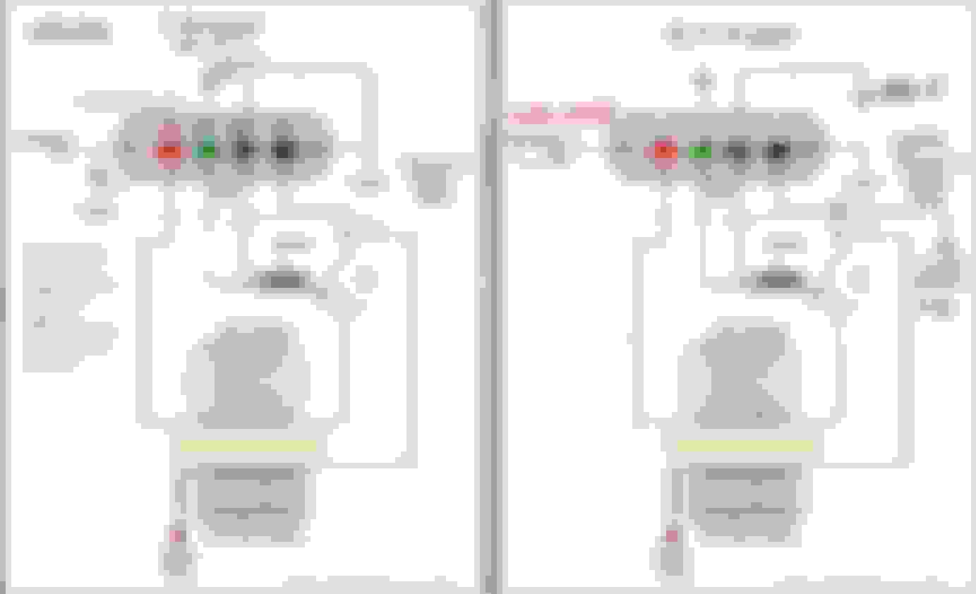
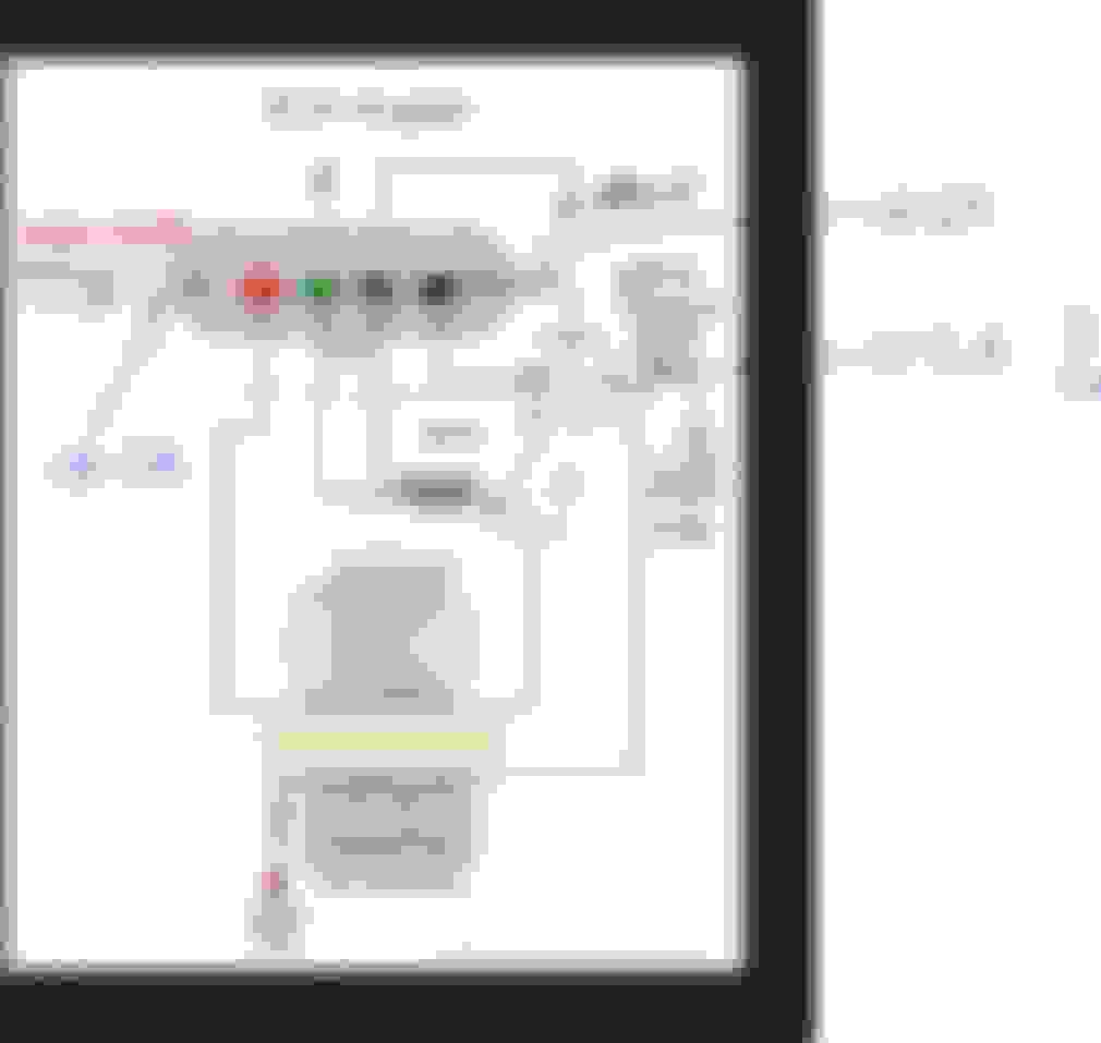
Before I show the scope result, I want to illustrate of how I think internally 3.0 Turbo COP is designed.
I borrow the image from here : http://www.megamanual.com/seq/coils.htm
I believe, the right side image I edited....is how 3.0 Turbo COP is wired internally.
These are the resistance check of my COP :
WILL CONTINUE.....................
.
Last edited by S-Prihadi; Jun 20, 2023 at 10:36 PM.
To clarify the direct connection of Pin 2 to COP needle and ring :
Visualization of wiring diagram of MB for M276.8 3.0 Twin Turbo COP
One would think that W16/5 is feeding the ECM with 3 x 2.5mm very big wire aside from all the COP coils, the W16/5 MUST BE the main negative power ground.
The answer is a YES and a NO, depending on which device it is for ? If for ECM, Yes, W16/5 is the main negative power wires or MAIN GROUND.
If for COP, it is a NO, W16/5 is not the the main negative power wires or MAIN GROUND
So if not W16/5 being the main negative power wire or MAIN GROUND, it must be W11 then ? NO, W11 is also NOT actually the main negative power wire or MAIN GROUND
W11 is placed there as back up or secondary ground for when and if main negative power wire or MAIN GROUND is lost....
So for my COP, what is then the main negative power wire or MAIN GROUND ??? The answer is, the freaking cylinder head !!!! That copper needle and ring is the MAIN NEGATIVE POWER GROUND connection.
GM does something something similar to W16/5 for its 4 wires COP.
It use the ground to send the firing confirmation, they call it Low Reference. Read here on page 49 PDF : https://opensiuc.lib.siu.edu/cgi/vie...text=auto_pres
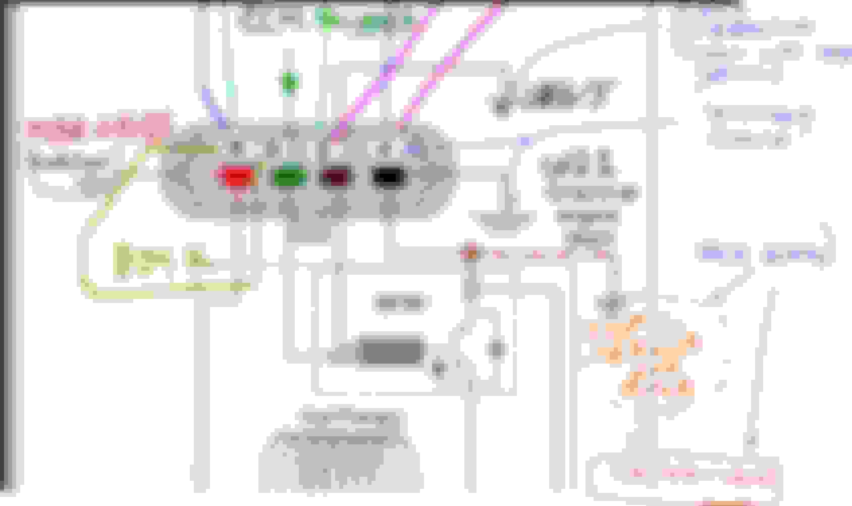
I added labels to visualize our COP if drawn on a GM COP, but missing the needle and ring Main Ground.
GM equivalent W16/5 ( Low Reference ) is not connected to chassis metal like our W16/5, but it is connected to PCM directly. Very similar to how Toyota 4 wires COP is, where the firing confirmation is sent out by
the COP and it is called IGF and is also wired to ECM and not to car chassis metal.
So Mercedes* ( *M276 3.0 Turbo ) for reasons I do not know, will need special sensing circuits to filter out the noisy ground to listen to the signal of firing of COP confirmation via W16/5. WOW, why ??????
The W16/5 on my engine, is a splice of 5 wires on a soldered lug/eyelet and connected to the chassis metal at firewall.
The 5 wires are : 3 for ECM , 1 for OBD Signal Ground ( yes DATA/SIGNAL GROUND ) and one more is from all 6 COP which has its own splice where all 6 COP pin 1 get connected and wired to W16/5.
So, I guess MB designer wants the OBD and COP signals to be as close as possible to the ECM and strangely they choose to use the ECM main negative feed as main signal carrier for the
signals sent out by OBD and all COPs firing confirmation.
.See pin 5 of OBD and U75 code where it shows W16/5 connection to pin 5, that is DATA/SIGNAL GROUND
The true main power negative feed for OBD is the pin 4, which is to the ground called W15/2 or W15/1 depending on car variant.
That W15/1 or W15/2 is a ground stud surely in the cabin of the car.
I first have to make a COP test connector before I can scope properly.
Now I can do whatever poking I want and no harm to my COP original wire and connector. Also more space to work with.
I can not yet find the FEMALE version of this connector, like the one found on the COP itself.
I only can get the male connector which is the wire harness side, original from MB. Made by Kostal.
Lets see the amperage value of Pin 3 ( fuse 24 positive power source ) and pin 1 the assumed main negative power source from W16/5.
Please look at V as volts and A as amperage. Imagine the waveform below is 2 DMM and 2 of current clamp data shown in 1 screen.
So pin 3 of fuse 24 is at 19.7 amps to fire the coil. Pin 3 or blue channel A can be seen its voltage drop when coil is starting to ramp up the current, we call this dwell time.
It is very short this dwell only 1 millisecond or 1/1,000 of a second. The bottom values on the image above are milliseconds. The entire screen above took place for only 5 milliseconds. No DMM can ever catch this signal.
Channel B in red, is the trigger command by ECM for COP to fire ....that is at pin 4 of COP. When ECM cut the 5volt, you see that Channel A blue starts to spike up to 19.x volts,
that is the collapsed of the magnetic field of the primary coil.
Channel D in orange, that is pin 1 or W1/65 which shows almost zero amperage.
By right if positive Pin 3 at Channel C Green shows 19 amps, the returns current on the negative wire Pin 1 Channel D Orange will be the same too, at 19 amps.
So here it showed that Pin 1 or W16/5 is not a current carrying wire for negative current. I was shocked. It then must be W11 as the main negative wire ?
=====
So I relocated the Channel D Orange for Pin 2, which is from W11.
I also relocated Channel B red to read Pin 2 ( W16/5 ) voltage signal, not amperage.
Channel A Blue is still the same voltage of Pin 3 ( fuse 24 ).
Channel C Green is still amperage of Pin 3 ( fuse 24)
Now here is what initially baffled me, as my assumption is still that Pin 2 to W11 is not the main negative feed, but it does shows 4.6 amps of current is flowing there, see Channel D Orange.
Now where is the missing amperage ? 19.7 less 4.6 amps = 15.1 amps ? Where is this path the 15.1 amps is taking ????
I assumed too much !!! Me brain was so stubborn to think that W16/5 was the main ground as such I became a dumb-azz
The total 19.7 amps which should be returning to ground, majority of 15.1 amps of it was using that freakin needle and ring of the COP, direct to cylinder head !!! Duggghhhh.
Whenever there are two conductors in parallel, even though 1 is tiny like the 1.5mm square of the W11 of approx 30cm run vs the big metal of the cylinder head and 1 millimeter away,
the current will be shared based on who has the least resistance, so cylinder head gets 15.1 amps out of 19.7amps or 76.6% and W11 or Pin 2 get 4.6amps out of 19.7amps or 23.4% = Total 100%.
Look at the Channel B Red of W16/5 , that is the COP firing confirmation signal at 2.8 volts, which looks like a simple noise.
So the ECM need to look at this "signal"....damn, that is one tough one.
But so you know, the inspection signal sent out to our engine sensors are also this small/low voltage and super short duration which initially I thought it was noise.
So, when one buy non genuine COP, the firing power maybe as good as MB genuine, but if the reporting circuit ( pin 1 ) is not to MB specification, the ECM may deem the COP is misfiring
simply because of the un-recognized confirmation signal sent out by the COP.
The firing and therefore the confirmation signal is not the same, it depends on RPM, coolant temperature and so on.
Here is a cold engine, COP fires 3 times in short duration. So the return signature would also be tailored to the firing events.
I did not scope pin 1 ( COP firing confirmation via W16/5), I was looking for difference after I clean the COP needle and ring and the their contact points at cylinder head.
See, now W11 is carrying less current at 3.2amps from previous 4.6amps before cleaning. 1.4 amps difference, not bad.
By cleaning the needle and the ring, the cylinder head now carry more current for the COP via that cleaner needle and ring of COP than the W11 wire or pin 2.
3.2 out of 19.6 = W11 share is now 16.3% only , no more 23.5%.
I hope this information is useful for even M276 3.5NA owners.
I do not know for sure about M276 3.5NA COP wiring scheme until I scope them the same way as I did to mine.
M276 3.5NA wire sizes at the COP led me to believe, it could be using W16/5 as main negative ground or...........the bean counter for M276.8 3.0 Turbo design team realized they can
save 1mm square worth of copper strand per COP at Pin 1.... ha ha ha.
END
Last edited by S-Prihadi; Jun 18, 2023 at 04:39 AM.
Reason: typo
THANK YOU very kindly Master Surya, now a few more things totally make sense with the COP circuit and OBD DLC GND.
great survey 👏
The 40MR are insulated
The 490KR is the protection diode
W11 is the noisy COP GND for PRIMARY winding.
W16/5 is the clean SIGNAL reference GND.
COP winding is grounded locally by its fastener.
COP has two distinct sections: logic trigger + transformer coil. GND is not shared to cut noise down.
> COP PWR harness improvements:
keep noisy power bundled away from everything else (sensors, controls, sifnal GND, LIN/CAN Networks). RF shield that bundle to GND if possible.
Feed the COP+12 through a nice 14Gauge (AWG) wire. this is houng to speed up the coil saturation a tiny bit.
W11 is the GND return of the 12VPwr feeding the coil primary so share same size conductor.
Considering COP fire multiple sparks, we best home run these COP+12 to the edge of block separated from main harness.... this is a "COP feed harness". (I mean you do NOT want to run a bus-rail around the V and hook up to a single loop or ring feed!) - Homeruns.
COP TRIGGER:
The trigger signal and GND are not noisy because they have no power throughout (10mA). They can be separate or bundled in main trunk. No change, no problem.
> DLC W16/5 GND : Two birds with one stone: here's a great opportunity to observe issues at W16/5 and W-TF Main Strap. The DLC signal GND drop-voltage can easily show the GND health under load.
I am not clear about differences between 3.0TT and 3.5NA coils - I got to re-read from the top plus the post#3 above.
🙏
Last edited by CaliBenzDriver; Jun 18, 2023 at 04:49 AM.
Thanks, interesting. 15.1A through a pin doesn't make sense to me.
Where exactly did you install the probe to measure 15.1A through the pin? Can you point to the location in an existing photo, or post a new photo?
Originally Posted by S-Prihadi
I first have to make a COP test connector before I can scope properly.
So I relocated the Channel D Orange for Pin 2, which is from W11.
I also relocated Channel B red to read Pin 2 ( W16/5 ) voltage signal, not amperage.
Now here is what initially baffled me, as my assumption is still that Pin 2 to W11 is not the main negative feed, but it does shows 4.6 amps of current is flowing there, see Channel D Orange.
Now where is the missing amperage ? 19.7 less 4.6 amps = 15.1 amps ? Where is this path the 15.1 amps is taking ????
I assumed too much !!! Me brain was so stubborn to think that W16/5 was the main ground as such I became a dumb-azz
The total 19.7 amps which should be returning to ground, majority of 15.1 amps of it was using that freakin needle and ring of the COP, direct to cylinder head !!! Duggghhhh.
See, now W11 is carrying less current at 3.2amps from previous 4.6amps before cleaning. 1.4 amps difference, not bad.
By cleaning the needle and the ring, the cylinder head now carry more current for the COP via that cleaner needle and ring of COP than the W11 wire or pin 2.
3.2 out of 19.6 = W11 share is now 16.3% only , no more 23.5%.
I hope this information is useful for even M276 3.5NA owners.
I do not know for sure about M276 3.5NA COP wiring scheme until I scope them the same way as I did to mine.
M276 3.5NA wire sizes at the COP led me to believe, it could be using W16/5 as main negative ground or...........the bean counter for M276.8 3.0 Turbo design team realized they can
save 1mm square worth of copper strand per COP at Pin 1.... ha ha ha.
Its a calculated number.
Input conductor, single wire = 19.7 amps
Return conductors , 2 conductors :
1 of 1.5mm wire to Pin 2 of COP to W11 which is 4.6 amps
1 block of cylinder head via the needle pin and installation ring of COP = X amps
Find X ......
That is why I showed by using continuity that the Pin 2 of COP is connected internally to the needle pin and installation ring, so reader would know the needle pin and the ring is a conductor too.
ADD : Dang I did not show that photo.
Here it is .............
I have coil extension wire 4 pcs, but too bad its size is for common "fat" spark plug size and not the mini spark plug my engine uses, so not use-able on my engine. https://www.picoauto.com/products/ig...set-of-4-leads
Otherwise I would use it and get another jumper wire to connect that COP ring to cylinder head and while at it, I can scope the true secondary coil waveform.
COP is a bi-etch to get its waveform.
Last edited by S-Prihadi; Jun 18, 2023 at 11:07 AM.
Reason: ADD INFO
Thanks. Sorry if you explained this, but in honesty your posts are very long and sometimes hard to follow for me. It's not the language, but rather the quantity of information. It's all very good and helpful for site members, just hard to gather. Maybe I am the only one, please forgive me if this is the case.
What vehicle conditions are the currents and voltages measured? Engine off? Engine idling? Engine at an rpm higher than idle? Thanks again.
No worry my man, the post has to be long , indeed lots of information.
I test amperage value with idling speed only because I do not want to damage my current clamps. The radiator fan heated up the clamps so badly.
Ignition only fires with engine running, that pin 4 trigger from ECM, the 5 volts trigger signal.
If pin 3 at ignition key ON engine OF ( KOEO ), fuse 24 will be powering pin 3.
Pin 2 W11 is permanently connected to cylinder head.
Pin 1 is permanently connected to firewall.
===============
Cali,
The voltage drop at pin 3 from fuse 24 is very small at 1.54 volts due to dwell time of only max 1 milli second or 1/1,000 of a second per firing. 0.9 milliseconds for below.
So I do not need to beef up the wire size, also them MLK 1.2 terminal can not handle beyond 1.5mm or AWG 16.
And no way I will remove my Front SAM where fuse 24 connector is at..... I am not delicate like you ... hahahaah
But can you imagine other cars with ECO active and while at 12.3Volts at battery..... that means at ECM harness to COP it would be 11.8V and 1.5V less for COP firing = 10.3 volts during COP firing.
Thanks. Sorry if you explained this, but in honesty your posts are very long and sometimes hard to follow for me. It's not the language, but rather the quantity of information. It's all very good and helpful for site members, just hard to gather. Maybe I am the only one, please forgive me if this is the case.
What vehicle conditions are the currents and voltages measured? Engine off? Engine idling? Engine at an rpm higher than idle? Thanks again.
You are not the only one. It's a lot of information to digest. S-Prihadi your industriousness is beyond impressive.
Thank you for this seriously advanced survey with still a few dark spots here such as...
Feedback... through W16/5: nop!
Wire sizing for pulse currents: fater!
Pardon some my limitations
1--- Dumbo Coils:
As far as we know ECU only has a unidirectional control pin to COP.
Our coils don't talk back to ECU neither through signal input pin nor through W16/5 output chassis GND.
2-- PWM wire sizing:
We don't like drop-voltages.... well here is where some performance limitations come from!
It's a common miss conception that you can average the short 1ms 20Amp current pulse over time period and say that a 5Amps wire is good enough!
The wire need to be sized to pass the peak of the pulse. When a significant resistance is present the top of the spike is also a ramp. That translates into a delay!
Law if diminishing retur informs us that we don't want to supersize the COP feed all the way to 20Amp DC, it's a burst of electric energy turning into an EMF through wiring radiation (current + flux = .... 90� force)
3--- W16/5 signal GND :
You know about optocopler components right? Power transistors are available with built-in optical control.
The primary power GND W11 is not connected to W16/5 by any the coils - The car itself ties these two GND through the W-TF strap, not the coils.
When the oxidized main strap begins to occur large drop-voltage, these 2 GND FLOAT APART. As far as the ignition it's no problem because of optocoupled floating W16/5 trigger signal GND.
You testing showed there is no current in W16/5 wiring as I predicted a 15mA to bias coil circuits.
4--- ECU 3x W16/5 shared GND eyelet :
We've seen how Painted GND Posts can become compromised for multiple reasons (eyelet obstructing pins, painted nut, oxidized post). The outcome is a resistive GND input floating above GND according to current passing through the poor resistive contact.
5--- Good for COP, bad for ECU :
The W16/5 eyelet has COP signal GND soldered to the 3x ECU GND Input. A poor GND post is only going to disrupt the ECU because the ignition GND remains referenced to ECU floating GND.
Thank you for this seriously advanced survey with still a few dark spots here such as...
Feedback... through W16/5: nop!
Wire sizing for pulse currents: fater!
Pardon some my limitations
1--- Dumbo Coils:
As far as we know ECU only has a unidirectional control pin to COP.
Our coils don't talk back to ECU neither through signal input pin nor through W16/5 output chassis GND. REPLY : WRONG
2-- PWM wire sizing:
We don't like drop-voltages.... well here is where some performance limitations come from! REPLY : YES AGREE
It's a common miss conception that you can average the short 1ms 20Amp current pulse over time period and say that a 5Amps wire is good enough!
The wire need to be sized to pass the peak of the pulse. When a significant resistance is present the top of the spike is also a ramp. That translates into a delay!
Law if diminishing retur informs us that we don't want to supersize the COP feed all the way to 20Amp DC, it's a burst of electric energy turning into an EMF through wiring radiation (current + flux = .... 90� force)
3--- W16/5 signal GND :
You know about optocopler components right? Power transistors are available with built-in optical control.
The primary power GND W11 is not connected to W16/5 by any the coils - The car itself ties these two GND through the W-TF strap, not the coils.
When the oxidized main strap begins to occur large drop-voltage, these 2 GND FLOAT APART. As far as the ignition it's no problem because of optocoupled floating W16/5 trigger signal GND.
You testing showed there is no current in W16/5 wiring as I predicted a 15mA to bias coil circuits. REPLY : Confirmation Signal is too small to measure with my 20/60A current clamp. Simply see the voltage, no need to see the current.
4--- ECU 3x W16/5 shared GND eyelet :
We've seen how Painted GND Posts can become compromised for multiple reasons (eyelet obstructing pins, painted nut, oxidized post). The outcome is a resistive GND input floating above GND according to current passing through the poor resistive contact. REPLY : YES AGREE
5--- Good for COP, bad for ECU :
The W16/5 eyelet has COP signal GND soldered to the 3x ECU GND Input. A poor GND post is only going to disrupt the ECU because the ignition GND remains referenced to ECU floating GND.
=====
NEW TEST - To confirm if Pin 1 of COP which is connected to W16/5 ground , does this COP issue a firing confirmation to ECM using such noisy ground wire W16/5 ?
Revised test wire kit. Now with interconnect for ease of signal or power intervention
This is diagnostic signal when engine is OFF, but ECM is awake after door opening or key in ignition.
So does the COP issue a firing confirmation to ECM using such noisy ground wire W16/5 ? YES YES YES
So , guys make sure your W16/5 is found and keep it clean and it has to stay clean.
As to connect or jumped W16/5 to W11 for "insurance", please don't. MB engineers seems to have tested that W16/5 is probably "cleaner" of noise than W11 which is at cylinder head with high voltages
radiation from COPs and Injectors and whatever other devices.
ADD : Also, connecting W16/5 with W11 can fry the ECU when and if the unnamed W-TF ground cable under the car to starter motor has bad contact or loose, therefore the ECM thru its W16/5 which is now
married to W11 will then pass the huge current via its internal ground trace at PCB board, because this marriage is the same as sending a small wire from firewall (W16/5) to cylinder head (W11).
This gets the worst effect when engine cranking because surge current peak/spkine can be 570 amps for my M276.8 3.0 TT and constant current approx 220 Amps.
Last edited by S-Prihadi; Jun 19, 2023 at 07:22 AM.
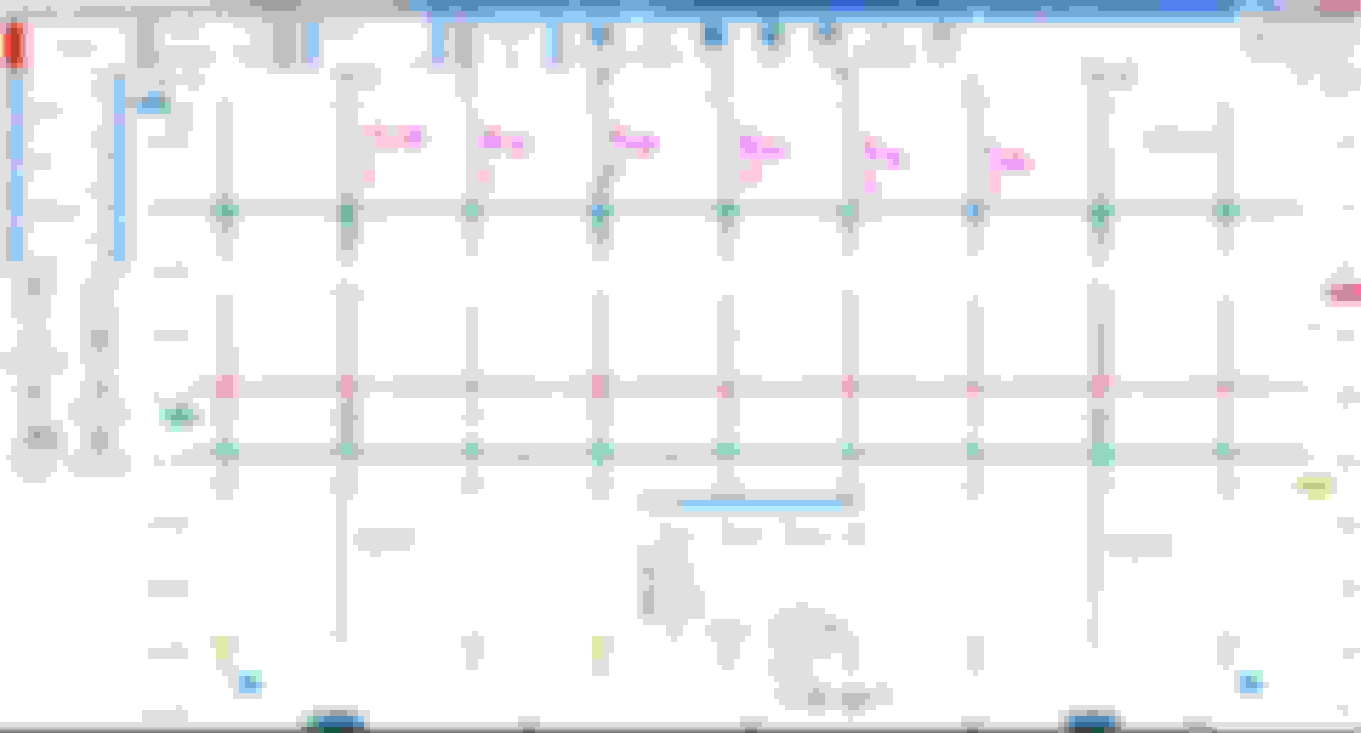
Interesting sparks ( & injectors too ) multi-firing strategy.
I do not know why some cylinders get 4 pulses and some get 3 pulses upon starting from COLD, me at 30C ambient. Last engine kill was 12+ hours ago.
Below is after engine run approx 10 seconds, hence RPM is still 708. My warm idle without AC is 550 RPM approx.
Perhaps these pulses depends on the fuel injector tolerance/calibration value ?
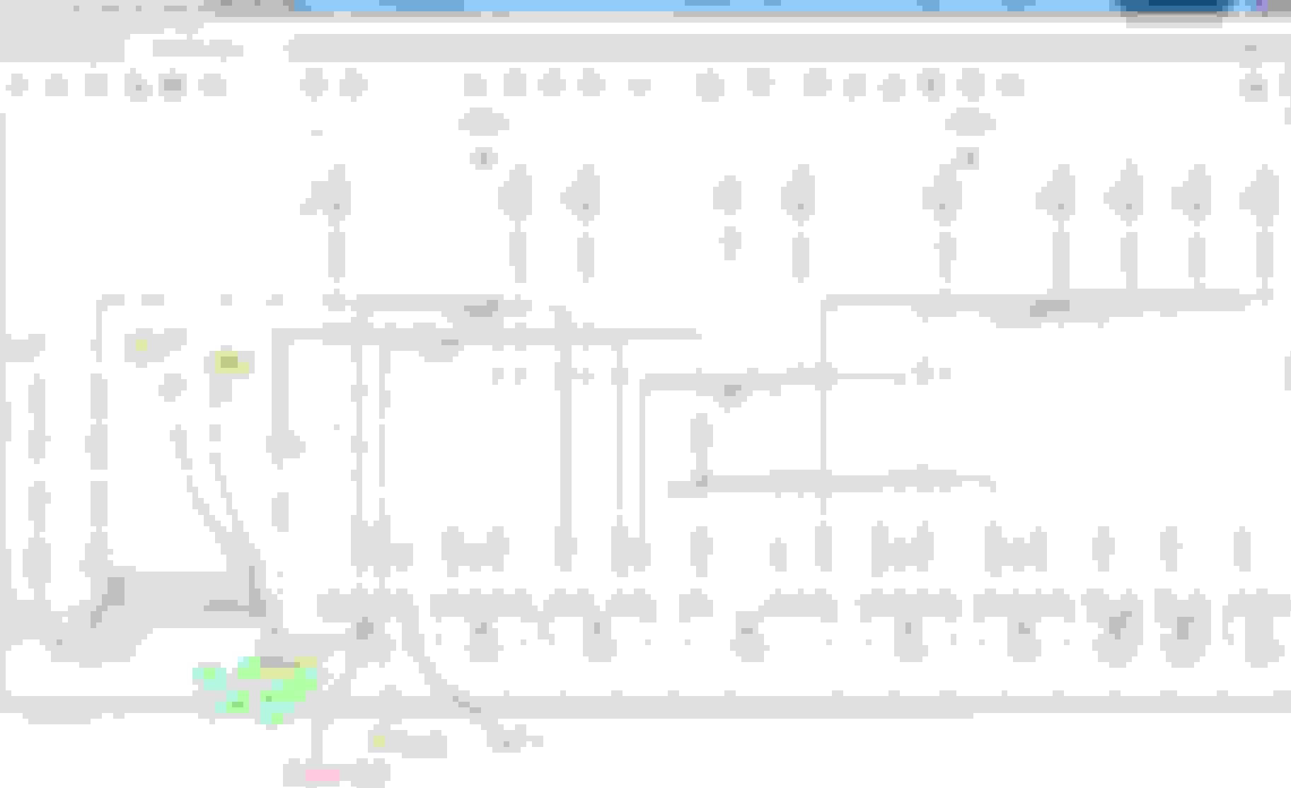
Below is M276 firing order.
LEGEND
Channel A Blue is PIN 3 ( Fuse 24 )
Channel B Red is Pin 1 ( W16/5 )
Channel C Green is Pin 2 ( W11 )
Channel D Orange is Pin 4 , 5V trigger from ECM
I have not disconnected the Pin 1 ( W16/5 ) of COP yet at this image capture, see page is 1 from 64 captures.
LEGEND
Channel A Blue is PIN 3 ( Fuse 24 )
Channel B Red is Pin 1 ( W16/5 )
Channel C Green is Pin 2 ( W11 )
Channel D Orange is Pin 4 , 5V trigger from ECM
A bit more zoomed image for 4 pulses and 3 pulses.
LEGEND
Channel A Blue is PIN 3 ( Fuse 24 )
Channel B Red is Pin 1 ( W16/5 )
Channel C Green is Pin 2 ( W11 )
Channel D Orange is Pin 4 , 5V trigger from ECM
The 4 pulses very zoomed.
Image capture page is at 35, one page is 0.5 second long. 35 x 0.5 plus the 10 seconds initial engine start which was not* captured. So approx 27-28 seconds into engine start. *Actually the scope buffer memory dumped those first few pages when it is already full, FIFO style.
So ECM is still doing warm-up strategy.
====================
MISFIRE
Let invite a misfire. I disconnected Pin 1 ( W16/5) from COP. Let ECM loose its "hearing" of firing confirmation.
LEGEND
Channel A Blue is PIN 3 ( Fuse 24 )
Channel B Red is Pin 1 ( W16/5 )
Channel C Green is Pin 2 ( W11 )
Channel D Orange is Pin 4 , 5V trigger from ECM
This is during the zoomed view of the misfire I created by disconnecting W16/5 from COP pin 1.
After Pin 1 is re-connected to W16/5 and no misfire, engine deemed warm enough to no more get multiple spark-injectors event. Now is a single pulse.
Page 64 of waveform is the last page.
LEGEND
Channel A Blue is PIN 3 ( Fuse 24 )
Channel B Red is Pin 1 ( W16/5 )
Channel C Green is Pin 2 ( W11 )
Channel D Orange is Pin 4 , 5V trigger from ECM
================================
Interesting view of my Bank 2 - LEFT wires being longer ( RHD car ) or/and possible the splice not too good, I get lower voltage read at Pin 3, +12V supply from fuse 24 compared to fuse 23.
LEGEND
Channel A Blue is PIN 3 ( Fuse 24 )
Channel B Red is Pin 1 ( W16/5 )
Channel C Green is Pin 2 ( W11 )
Channel D Orange is Pin 4 , 5V trigger from ECM
Bank 2 is having more voltage drop each time the COP fired, compared to Bank 1.
Bank 1 voltage drop from 14V to 13.64 is only 0.36 volts as highest drop.
Bank 2 voltage drop from 14V has up to worst case down to 12.46V, meaning 1.64V drop. Let say 1.5V average drop.
Electric load for Fuse 23 vs F24 is equal.
Front SAM fuse terminal "bite" can also be partial culprit.
Front SAM to wire harness connector the female and male terminal, can also be partial culprit.
Surely longer wire run is guaranteed to increase voltage drop and is so obvious all Bank 2 COP are running at lower voltage during COP peak load.
That's all for today
Last edited by S-Prihadi; Jun 19, 2023 at 09:07 AM.
Reason: ADD INFO
As expected, nothing will happen as long as we keep the needle pin and the brass/copper ring clean and its contact point at the cylinder head clean.
Here is a unique finding. I think this is because 1st cylinder is the first cylinder in the firing sequence and the ECM is doing some sort of diagnostic or whatnot and cylinder 1
seems to be the reference.
Engine just started, 0.584 seconds ago. That time code is 1/1000 second for its 3 digits after decimal.
Cylinder 1 no issue.
4.8 seconds later at 5.372 seconds ( including whatever Xentry system lags in displaying ) , there is 1 misfire count for cylinder 1.
The first 5 seconds of engine start surely is higher RPM as seen, up to from 1,299 to 1,318 RPM.
Usually I know I can sense a very very very little not so good combustion but very short duration for the first 10 seconds of engine start.
I guess this is what I been sensing all along and now I can see that indeed there is 1 misfire count.
At 61.995 seconds the ECM has not updated the status yet.
Within 0.2 seconds later, at 62.195 seconds, the ECM removed the misfire count and its back to zero.
Our flywheel is a 58 + 2 empty tooth = 60 tooth or 5 degrees CKP resolution per teeth, considered a very high resolution.
If engine spin twice, guaranteed ECM will know where ZERO is.
Cranking speed is approx 200 RPM, so within 1 minute ECM has seen 200 times crankshaft spun or within 1 second 3.3 times the crankshaft has spun.
I recalled in ECO 101 document, ECM remembered where crankshaft stop ( easy for ECM ) as such re-starting can be very smooth.
I think this test have answered my own questions on the not so good combustion at cold start within the very first few seconds due to combustion still very cold,
but I am still wondering it is cylinder 1 being indicated by Xentry because of firing order where cylinder 1 is the start of count, and thus cylinder
1 is the unlucky cylinder being tasked to first fire and then the blame is on cylinder 1...?. LOL
Secondly, why it takes 5.3 seconds for Xentry to declare 1 count of misfire count on cylinder 1 ? Or that 1 count of misfire occurred at 5.2 seconds ?
If we take average RPM of 1,300 for 5 seconds engine has been running COLD, cylinder 1 would have fired 1,300 / 2 ( 4 stroke ) = 650 / 60 second per minute = 10.83 firing event per second.
So for 5 seconds there would be 54 firing events at all cylinders already or 108 revolution of the crankshaft .
To why only after 57 seconds later, the misfire counter at cylinder 1 goes back to Zero , I think I know the answer to that.
Total 57 seconds at 1,300 for some 15 seconds or so and then slowing down progressively to 700 RPM =
1,300 / 60 * 15 seconds = 324 times flywheel has spun
700 /60 *42 = 490 times flywheel has spun for the last 42 seconds
Total approx 814 revolution of crankshaft as rough count.
Its close to the 1,000 revolution of crankshaft for misfire monitor. I guess 1,000 revolution is the block used for reset too, per 1,000 revolution no issue and then reset to zero count again.
Okey, now the W11 or Pin 2 of COP, disconnection real time in video.
Fascinating stuff. Thanks for sharing! So to be clear Xentry is required to provide this information, Correct?
No.... you need a 4 channel PicoScope 4425A for the waveform test I did.
Minimum US$3,000 with the accessories you need https://www.aeswave.com/4-Channel-Pi...178-p9836.html
I got more stuff than above links above, and I bought bit by bit overtime.
You still need a proper but clone Xentry, get the Benz-Ninja version is iso freakin fast and is not expensive at all including BenzNinja lifetime service,no more than US$1,000 , inclusive of a used laptop for the Xentry maybe from Craiglist.
In regards to post#12:
We see voltage in GND so that makes me wonder where is the scope GND referenced to?
It should be W11 or directly to the engine block.
GND SHOWS VOLTAGE!
Both W11 & W16/5 GND inputs should show flat like a pancake unless youhave a floating GND reference issue.
Understand each scope digital inputs is measuring a million samples that are saved in a buffer for display. If measurement are meaningless then the graph is meaningless.
Right now you're measuring dynamic voltage without a reference voltage, usually a good reference GND is the engine. Here we don't want to visualize statics in W-TF strap so we don't GND on chassis, we GND on block for ALT reference.
Once you have that GND reference solved then you can begin to trust the inputs measurements you are scoping.
U
coil feed wiring
Here are some opportunities for ignition wiring improvements:
-- Bank2 distribution path was made longer than Bank1... make it equal now to help keep bank1 & 2 balanced.
-- Make an equal distribution from Cyl5 to (4;6) and Cyl2 to (1;3).
-- Homerun towards F-SAM fuse with a 14 or 12 AWG to minimize resistance drop for the 20Amp spikes. You don't need to replace wiring all the way... you can keep couple inches 5cm to splice existing fuse output without any crimping needed.
Fuse sizing: 15A vs. 20A... similar loads
It looks like the fuse loads are identical but MB used different fuse protection... that means different voltage-drop from serial resistance, right?
Here bump both to 20Amps.
Thank you:
Last edited by CaliBenzDriver; Jun 19, 2023 at 03:37 PM.
I would go down to 15A first, and see if the system works. If it blows, we then know the listing is misleading, and conclude that there is more load on Fuse 23 than is listed in the document. Safe than sorry.
I would go down to 15A first, and see if the system works.
If it blows, we then know the listing is misleading, and conclude that there is more load on Fuse 23 than is listed in the document.
Safe than sorry.
yeah true, nothing's ever simple
I choose to bump the 15A to 20A so we don't get to power down half banks of the engine.
The soft fuse link does register passing the 20A ignition spike, if you undersize that fuse it will slowly age the soft link into crumbles.
This fuse is not passing a nice DC load, it is suppling the COP and VVT PWM solenoids: all inductive loads with tons of switching spikes.
(Nice post#14: later)
Last edited by CaliBenzDriver; Jun 19, 2023 at 03:54 PM.
I understand, it is just me being extra cautious with fuses.
Once an AC technician came to repair the 2nd floor AC unit, and he thought the blown 3A (240V rated) fuse was the only problem, and replaced by a 5A fuse. In the morning (@7AM), the thermostat was in flames burning the wall paint and the house with the nasty burned wiring insulation smoke.
Call the AC service company and mentioned the problem. Technician in the house in less than 45 minutes, found the problem: contactors on the AC external unit, replaced them, new capacitors, new thermostat, cleaned the unit again, and checked the 1st-floor unit as well. The bill? Sincere apologies, and do not worry about payment.
OMG Juan, that what you call lucky to spot the issue early before a house fire started.
I usually don't like super sizing fuses but here it looks like MB when out of its way to help imbalance both engine banks. Surya reported the COP wiring is 1 long + 1 short and the two fuses are different for the exact same load.... (W-TF!)
We need to have bith banks balanced at all cost otherwise the difference helps creates engine vibrations.
> HOME AC... fix:
The 3Amp fuse was protecting the control side only, right?
The compressor in-rush is around 60Amp with "only 20A" runtime current for compressor plus condenser fan.
The Locked Rotor Amp current kills the AC contactor and the dual-cap (start+run) after years in service.
It slowly gets derated and causes current imbalance in both compressor windings.
The best solution is to upgrade the compressor starter with a "slow starter". It ramps up current, starting from zero to runtime instead of down from LRA extreme spike.
The outcome is extended service life for :
compressor bearings
dual-cap
contactor now switching at zero Amp
Any single phase AC motor, pumps and all with a run-cap benefits from "slow-starter".
Here is a good video
+++++
I got a lill story about "AC breakers"...
Couple years ago I was installing a new ceiling light fixture atop of the lader in my home stairs... (lader + stairs... you know: unstable!).
I was putting in the last screw when all of the sudden a giant blue flash blinded me like... hell just happened??
I found out that I had driven a fastener in the live black flippin' wire, not the Neutral, nop, go figure it out !!!
long story short: the 30year old braker did nothing , it was still ON after a dead short that melted, exploded the live wire in the fixture.
So i replaced the 20 amazing GE brakers in my entrance electric box with all new Schneider-SquareD including two GFCI Brakers for Jacuzzi tub.
Last edited by CaliBenzDriver; Jun 20, 2023 at 02:29 AM.
OMG Juan, that what you call lucky to spot the issue early before a house fire started.
I usually don't like super sizing fuses but here it looks like MB when out of its way to help imbalance both engine banks. Surya reported the COP wiring is 1 long + 1 short and the two fuses are different for the exact same load.... (W-TF!)
We need to have bith banks balanced at all cost otherwise the difference helps creates engine vibrations.
> HOME AC... fix:
The 3Amp fuse was protecting the control side only, right?
The compressor in-rush is around 60Amp with "only 20A" runtime current for compressor plus condenser fan.
The Locked Rotor Amp current kills the AC contactor and the dual-cap (start+run) after years in service.
It slowly gets derated and causes current imbalance in both compressor windings.
The best solution is to upgrade the compressor starter with a "slow starter". It ramps up current, starting from zero to runtime instead of down from LRA extreme spike.
The outcome is extended service life for :
compressor bearings
dual-cap
contactor now switching at zero Amp
Any single phase AC motor, pumps and all with a run-cap benefits from "slow-starter".
+++++
I got a lill story about "AC breakers"...
Couple years ago I was installing a new ceiling light fixture atop of the lader in my home stairs... (lader + stairs... you know: unstable!)
I was putting in the last screw when a blue flash blinded me like... hell just happened??
Exactly 3A fuse was on the control board of the air-handler. If I recall correctly, the contactors stayed too long and because the fuse was oversized the thermostat acted as a fuse while burning.
I understand you fell, . Being on the ladder, and doing lamp as well. Do not like anyone around because of Murphy's law, and I double-check panels, switches, volt test and certain nobody walks in the garage while I am messing around with wires --> Paranoia when working with electricals.
In regards to post#12:
We see voltage in GND so that makes me wonder where is the scope GND referenced to?
It should be W11 or directly to the engine block.
GND SHOWS VOLTAGE!
Both W11 & W16/5 GND inputs should show flat like a pancake unless youhave a floating GND reference issue.
Understand each scope digital inputs is measuring a million samples that are saved in a buffer for display. If measurement are meaningless then the graph is meaningless.
Right now you're measuring dynamic voltage without a reference voltage, usually a good reference GND is the engine. Here we don't want to visualize statics in W-TF strap so we don't GND on chassis, we GND on block for ALT reference.
Once you have that GND reference solved then you can begin to trust the inputs measurements you are scoping.
Ground Reference for scope. Its there on the photo at post #11.
Here is a close up. It is the W10 brass stud near the battery, that is the most upstream ground on our car.
I won't use battery post negative because it will bypass the Hyundai battery sensor and it is not the ground ECM is seeing .
I would also not use engine block W11 as ground for this test, it is not upstream enough.
Since I am measuring ground voltage at Pin 1 and Pin 2, W10 is the best scope ground reference and Bernie Thomson of ATS would spank me if I do not use W10
If I scope a 3 wire 5V sensor, I use the sensor own ground because often the 5V has filtered circuits and is cleaner than W11 engine block ground.
When you have the chance to use Pico 4425A, its 12 bit vertical resolution and its capture detail...plus all the noises of the engine, you will see a lot of activities on any other ground wires referenced to W10 ground.
I wonder how an ATS Elite 4 16 bit version would be.... must be more awesome and more awesome if any automotive scope can have its own internal memory worth 3 minutes capture at max detail.
My 8 bit vertical resolution low cost Pico 2205A does not have the resolution, I missed or rather un-able to see a lot of small signals when using it for a same tougher test vs the 4425A.
======================
On the voltage drop at Bank 2.
I must see how long a wire run from COP 4, 5 and 6 , Pin 3 (+12V) to its splice Z7/35z1 and this splice to Front SAM fuse 24.
I won't want to tear open the wire harness to trace the Z7/35z1 wire to fuse 24 any further than the already exposed area of the wire tray. Front SAM is off limits for me.... I am not blessed with your delicate fingers.
Z7/35z1 splice to fuse 24 at Front SAM by diagram is supposedly a 2.5mm wire.
Your option of replacing the Pin 3 wire of 1.5mm with a fatter one by means of soldering to say -5cm away from the COPs is also a good idea.
I actually have SLK 2.8 female terminal of 2.5mm wire size. COP uses SLK 2.8 and I can do full 2.5mm wire from splice Z7/35z1 to Pin 3 of COP,
but I do not have the correct silicone seal, no stock at my usual German stockist.for like 4 months now.
This Kostal SLK 2.8 female terminals have 3 sizes for its wire use, up to 0.75mm, up to 1.5mm and up to 2.5mm.
Correct wire size must be used for the terminal, otherwise the crimping result would be bad because the crimp "ear" varies in size depending on wire size designation.
I will solder after the crimping of course, but I need to make sure I use all correct size one.
Lets wait for my SLK 2.8 extraction tool to arrive from Germany in 2-3 more weeks and I will re-visit this voltage drop thingy.
Thanks Cali....
I would go down to 15A first, and see if the system works. If it blows, we then know the listing is misleading, and conclude that there is more load on Fuse 23 than is listed in the document. Safe than sorry.
Front SAM for W212 is a *****, it serves many variants.
So as to why Bank 1 fuse 23 is a 20 amps instead of the same 15 amps of Bank 2 , is more of convenience of MB.
Must see the Front SAM 10 pages and study them to all engine variants available and read all engine's ECM wiring too,
because my engine's Fuse 23 Bank 1 could be also serving more devices in other engine variants.
The M276 3.5NA also get 20 and 15 amps for their banks 1 and 2
Last edited by S-Prihadi; Jun 20, 2023 at 02:50 AM.
Ground Reference for scope. Its there on the photo at post #11.
Here is a close up. It is the W10 brass stud near the battery, that is the most upstream ground on our car.
I won't use battery post negative because it will bypass the Hyundai battery sensor and it is not the ground ECM is seeing .
I would also not use engine block W11 as ground for this test, it is not upstream enough.
Since I am measuring ground voltage at Pin 1 and Pin 2, W10 is the best scope ground reference and Bernie Thomson of ATS would spank me if I do not use W10
If I scope a 3 wire 5V sensor, I use the sensor own ground because often the 5V has filtered circuits and is cleaner than W11 engine block ground.
When you have the chance to use Pico 4425A, its 12 bit vertical resolution and its capture detail...plus all the noises of the engine, you will see a lot of activities on any other ground wires referenced to W10 ground.
I wonder how an ATS Elite 4 16 bit version would be.... must be more awesome and more awesome if any automotive scope can have its own internal memory worth 3 minutes capture at max detail.
My 8 bit vertical resolution low cost Pico 2205A does not have the resolution, I missed or rather un-able to see a lot of small signals when using it for a same tougher test vs the 4425A.
======================
On the voltage drop at Bank 2.
I must see how long a wire run from COP 4, 5 and 6 , Pin 3 (+12V) to its splice Z7/35z1 and this splice to Front SAM fuse 24.
I won't want to tear open the wire harness to trace the Z7/35z1 wire to fuse 24 any further than the already exposed area of the wire tray. Front SAM is off limits for me.... I am not blessed with your delicate fingers.
Z7/35z1 splice to fuse 24 at Front SAM by diagram is supposedly a 2.5mm wire.
Your option of replacing the Pin 3 wire of 1.5mm with a fatter one by means of soldering to say -5cm away from the COPs is also a good idea.
I actually have SLK 2.8 female terminal of 2.5mm wire size. COP uses SLK 2.8 and I can do full 2.5mm wire from splice Z7/35z1 to Pin 3 of COP,
but I do not have the correct silicone seal, no stock at my usual German stockist.for like 4 months now.
This Kostal SLK 2.8 female terminals have 3 sizes for its wire use, up to 0.75mm, up to 1.5mm and up to 2.5mm.
Correct wire size must be used for the terminal, otherwise the crimping result would be bad because the crimp "ear" varies in size depending on wire size designation.
I will solder after the crimping of course, but I need to make sure I use all correct size one.
Lets wait for my SLK 2.8 extraction tool to arrive from Germany in 2-3 more weeks and I will re-visit this voltage drop thingy.
Thanks Cali....
> Smart ECU control : ECU many ignition parameters
It's really nice to see the fault conditions criteria. Tons of parameters are used to manage spark timings.
Also super nice when the engine stops, the ECU knows precisely what positions engine shafts are in. Now ECU remembers positions accross restart.
> AWSOME STUFF :
I believe I understood why you think the COP have a sort of feedback out to ECU the way scope is showing activity. You have covered an extreme amount of knowledge, research and data - Here included with the cops. Great many thanks to you I think I understand the single/multi sparks for cold/warm engine.
> SCOPE GND: scoping a RHD princess
Great choice to keep all inputs GND together as the same potential. This cuts down on problems without complications.
We ground the scope with what we are scoping at the same power negative tied to the source negative through the common ground.
HERE IS THE SAVE YOUR BACON NOTE: (I think you are aware if it... good to keep in mind - NO BIG BANG!)
Laptop USB port
Xentry plugs in DLC GND at W16/5
Dc-Power maintainer
Any battery charger
SCOPE power supply
aboves are all potential enemies ready to spark new challenges for ya
What happen is some of these devices reference the AC Main GND or Neutral right through. When two accessories are trying to force a different common voltage, the looser is the little guy, not the 40A maintainer.
Keep scope GND together so they don't carry any current, only 0 curremt reference voltage to scope input.
> GND not Zero... :
okay I see you are grounding at W10 Chassis-GND, precisely "W-TF strap" away from the COP engine GND... true?
The W10 Chassis-GND and W16/5 Chassis-GND should be exactly identical unless one is compromised.
Chassis = Chassis , right?
If you scope the W10 GND post do you see same noise as W16/5 GND post -or is it the unshielded scope input test lead that's picking up noise?
W11 showing noise maybe caused by what is going through the W-TF strap to source.
I don't understand why you say "battery GND W10 is the most upstream", with engine runing the upstream source is ALT grounded to engine block = W11.
Last edited by CaliBenzDriver; Jun 20, 2023 at 03:32 AM.
Front SAM for W212 is a *****, it serves many variants.
So as to why Bank 1 fuse 23 is a 20 amps instead of the same 15 amps of Bank 2 , is more of convenience of MB.
Must see the Front SAM 10 pages and study them to all engine variants available and read all engine's ECM wiring too,
because my engine's Fuse 23 Bank 1 could be also serving more devices in other engine variants.
The M276 3.5NA also get 20 and 15 amps for their banks 1 and 2
ok, you don't need to look at all the MB chassis variants, here you shortcut ...
It makes you wanna scope these fuses (feeding COP + Solenoids) to see how much of what type of signal is going through these noisy fuses.
Chassis W10 vs. Engine block W11:
This is the "W-TF main Strap" shows the voltage difference between block vs. chassis loaded with engine fan & more...
We expect nearly insignificant voltage difference below 100Amps or near max load (besides the 650Amp starter )
👏
Last edited by CaliBenzDriver; Jun 20, 2023 at 05:33 AM.
Mercedes SLR McLaren 722 S Is Extremely Rare Example Modified by McLaren
Slideshow: A one-of-one U.S.-spec Mercedes-Benz SLR McLaren Roadster became even rarer after a factory-backed transformation at McLaren's headquarters.


 , indeed lots of information.
 .
.