When you click on links to various merchants on this site and make a purchase, this can result in this site earning a commission. Affiliate programs and affiliations include, but are not limited to, the eBay Partner Network.
I'm busy upgrading the charge cooling system for my S4 and read this thread with much interest. I received the proper datasheets from MS Motor Services for the CWA pumps, describing the control of the pump duty cycle. I attach two pages here for interest. This also shows that while it is possible to run he pump with +12V on he PWM input the pump isn't designed tomoperate like that and instead of running at 100% duty cycle, it will run at about 97% as indicated by one of the other forum members.
It is probably academic as 97% would be ample I think.
Thanks to Nick's efforts I was able to order a tinyCWA controller from Tecomotive with custom firmware for manual control of my pump speed. The OE pump on this car - a CWA50 - runs at 50% duty cycle normally and reprogramming the algorithm in the ECU is possible but I haven't been able to source the necessary security access code for that.
I'm fabricating a custom heat exchanger locally which has about 2.5 times the surface area of the stock unit, and with the help of the controller I will optimise the pump speed for acceptable control of IAT for our conditions.
I got some solid ideas reading this thread - including keeping the stock Pierburg pump as opposed to what was initially suggested by others...great work Nick!
Its definitely not a CWA-50 or CWA-100. Its an engine cooling pump, rather than an intercooler pump. You can tell by the large inlet & outlet diameter. From the configuration of the electrical connector, I'd say it wasn't a Pierburg pump either. It looks like a Siemens/VDO pump; the type that's used on the 3.0 turbo engine. I don't know how you would control that. Can't help much I'm afraid. I'd write down the part numbers and put Google to the test.
Nick
Last edited by Welwynnick; May 27, 2015 at 05:29 PM.
I have the EWP-80 sitting around for almost a year now. Has anyone here ever mounted one in their E55 AMG? I'm curious of you guy's way of how you did it. Since the OEM way of attaching it with the OEM Bosch pump screw is not possible and before I go all out of my way designing and building a mounting adaptor. I hope someone has a solid idea or way of how he did it.
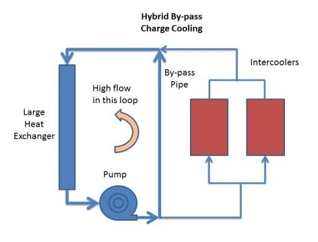
So how can you best use a high-flow pump in a charge cooler system? I had a crazy idea last night, thinking about how to make the most of my BMW coolant pump. This is a Pierburg CWA-200, which generates about 0.5 bar pressure over a wide range of flow rates. Indeed, the optimum operating point is around 120 lpm/32 gpm @ 0.5 bar, which is much more flow than I'm using (see post 108) So I thought about better ways to take advantage of the Pierburg's capability. Even if it was flowing much faster, it would still generate much the same pressure (more even), and that's what's necessary to keep water flowing through the IC's. Regardless of what's happening elsewhere in the system (double pumps, double HE's, whatever) the IC simply needs to "see" the right pressure and flow.
So I thought about running a by-pass pipe directly from the pump outlet to the HE inlet, by-passing the IC altogether. Doesn't make much sense, huh? Surely you want all the water to go through the IC? My thinking was it would increase the flow through the pump and get it working closer to its preferred pressure/flow point. It would increase flow through the HE, but because the CWA-200 has such a flat output curve, it would maintain output pressure at the higher flow rate. Therefore the IC flow wouldn't be affected, but the flow through the HE would be increased, which is a real benefit.
The increased HE flow interested me, but the by-pass to the HE inlet didn't make so much sense, as it would tend to increase the dynamic pressure at the inlet, and reduce the pressure differential across the IC. It was getting late and I wasn't thinking clearly, but I put my head down and things instantly became clearer.
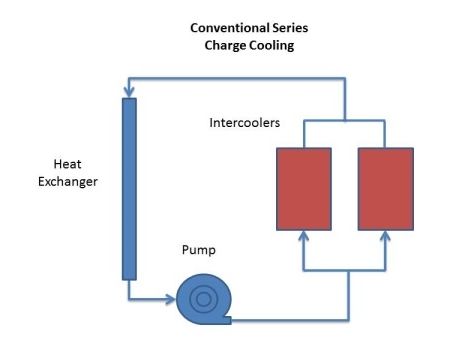
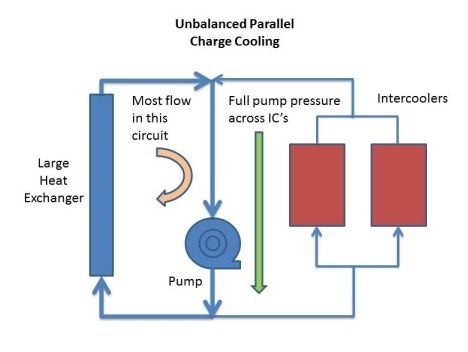
IC systems have high resistance, and its been difficult to cope with that all along. Maybe because of the IC, maybe the HE, maybe the inadequate 3/4" piping. But the thing is they're all in series, with resistance adding up. Why not simply connect them in parallel instead of in series? The two IC's are effectively in parallel with eachother already, so what will putting the HE in parallel do? The ICs will see all the pressure generated by the pump, but the flow through the HE will be higher. My HE is a BMW X3 radiator, which should take the full flow of the CWA-200 - which should be several times higher than the flow through the IC. On average, that means the coolant will pass through the HE several times, for every pass through the IC. It should reduce the temperature of the water going through the IC, due to the repeated HE passes. And as long as the pump is big enough, it should actually increase the flow through the IC, as the pump's output pressure isn't split across both the IC & HE - they both see the full pressure of the pump.
Of course, a proportion of the heated water from the IC will go through the pump and go straight back to the IC without going through the HE. But as long as the HE flow is much higher than the IC flow, most of the water going to the IC's will be extra-cold: colder than it would have been from a single HE pass.
So there's a thought - running the IC and HE in parallel instead of in series. Can that make any sense at all!?!?
The reason it might be a good idea is to make the most of what you've got. The charge coolers are an integrated part of the engine - upgrade them and you have no room for large air filters and cold air inlets, which undermines the benefit of the bigger IC's. The pump and HE are easier to upgrade, and can achieve similar improvements. An IC system is simply a very big heat sink for the charge air, and you want to minimise the thermal resistance between the intake air and the ambient air, so that you maximise heat flow outwards.
An air-to-air system is actually quite good at this, as there's very little between the two air streams - just a thin sheet of finned ally with a reasonable thermal resistance. A water cooled system is rather different, as you have to add to this an interface with the water in the IC, plus an interface with the water in the HE, plus the circulation system. All of that can only add to the thermal resistance of the whole system, so you need to minimise the resistance at both the IC and the HE.
Increasing the flow through the IC helps, but its difficult to make big improvements. Having a large heat exchanger and lots of flow WILL make a big difference to the HE however, and provide lots of cold water for the IC's. So the thermal resistance of the HE cannot be too low - even if the water was circulating at a million mph, it will still be worse than air-to-air, as it can only add to what's already there. Radiators normally run at a temperature delta between inlet and outlet of around 10 degC / 20 degF. So that's one delta for the HE, and one delta for the IC. Ideally, both will be zero, but the idea of a big HE and a big pump is to get that 10 degC delta as close to zero as possible.
Of course the V12TT uses charge cooling for packaging and piping reasons, but there are other advantages. The water passages in the HE are narrower than air passages, allowing MORE rows for a given frontal area. My X3 rad has fifty rows - more than any air-air cooler - and there's less obstruction to ambient air passing through, so other things being equal there will be more through-flow. Similar arguements apply to the IC's as well.
Nick
Nick,
What did you end up doing - parallel or left the system HE and IC in series?
I'm still using a series configuration, but I'm thinking about changing that. I use a CWA-100 pump, which is quite high pressure / low flow, but I'd like to go back to the CWA-200, and make the most of the engine radiator HE.
Before I do that though, I'd like to get some better instrumentation in, and at least have an in-line flow meter in series with the IC's. I do like the idea of having a really high flow through the HE (literally off the chart), and getting the thermal resistance down low, but I'd want to be sure that I wasn't reducing the flow to the IC's.
With charge cooling, you really want both elements of the equation to be low - ie: low thermal resistance for both the HE and IC. However, they don't have to be similar, they both simply need to be as low as possible.
The only slight problem with asymmetric shunt cooling is keeping the HE loop as short as possible. Most radiators are cross-flow, but a double pass rad like the E-class 6-cylinder cars might be a good idea. That would keep the feed and return hoses short. However, that radiator flow resistance would be higher, which undermines some of the advantage. The alternative is to stick with the cross-flow rad, and have the feed pipe running across the rad. Problem is there's not much room down there.....
Nick
Last edited by Welwynnick; Nov 9, 2015 at 05:23 PM.
Quick summary from another thread about how to install pumps in general:
I learned a lot about pumps and cooling systems in the last year or so.
Cooling systems have been developed over a hunderd years, its a problem that's been solved.
However, Mercedes seem to have forgotten all about it with the V12TT, and treated it as a special case, which is very unfortunate.
There are some long-established golden rules for installing (centrifugal) pumps, including:
The pump inlet pressure should be as high as possible.
Therefore the pump should be located at the lowest point in the system.
Locate the pump after the radiator, to keep it as cool as possible.
Mount the pump horizontally, to minimise bearing end loads.
To avoid air locks, the outlet should be at the top of the pump, and must not point down.
The pump's pressure/flow characteristics should be matched to the system resistance curve to achieve best performance.
Don't run a pump into an excessively high or low resistance, or it will fail quickly.
Keep air and contaminants out of the system.
Finally - feed the pump from the BOTTOM of the radiator, to minimise air ingestion.
It's the inlet that should be at the top of the HE (but maybe that would interfere with the LHS engine air intake on the V12TT). Either way, there ought to be a bleed facility at the top of the HE, whether its an automatic bleed to a header tank, or a manual bleed port like the end of the return pipe (near the ABC pump).
But yes, people often see an improvement in the performance of their IC system simply because its been bled properly, rather than because of the modifications they've done. I can't think of any other reason for the popularity of marine circulation pumps and engine cooling pumps.
I just stumbled across what might be the ideal HE for a tuned S600 (apart from the S65 HE, that is). My wish list includes:
Standard production radiator with aluminium matrix, and plastic tanks (so its cheap)
RHS Oil cooler for auto transmission (so I can run ABC oil through it)
Drain plug for bleeding
RHS High inlet
LHS Low outlet
Width: 600mm
Height: 500mm
Thick: 40mm
The Mercedes W124 diesel auto radiator is very close, but the inlet & outlet are in the extreme corners, so its difficult to clear the grille & hood when they're closed.
The Range Rover Sport 2.7 radiator seems to fit the bill, so this might be my next project. That's 12 litres of HE matrix volume, exactly the same as the engine radiator, and twice the engine capacity, it meets every criterion for me. The frontal area is also very large - even larger than the BMW X3 radiator that I currently use - so it should maximise airflow.
I think I might use the CWA-200 and SFR controller this time round.
Yes, its bigger than the stock S600 HE. I think the dimensions are somewhere in this thread.
According to Nissens, that little 122 bhp 1.4 TSI engine has a 620x410x16mm HE - about half the volume of the air-air IC, and amounts to 4067 cc volume. The stock S600 HE is 3228 cc.
Nick
Last edited by Welwynnick; Feb 17, 2016 at 03:47 PM.
what role does the pump on the drivers side (US model) have ? my SL65 has two pumps or is that for something else. The bosch 010 pump is there but there is also another pump part number A0001405385. Also "Nick" I have removed the 010 pump and am in the process of reinstalling it, whats the best method you found to feed it with least air pockets sir?
There's only one IC pump. I don't know what the other pump is, maybe the emissions air injection pump. Bleeding the IC system properly is almost impossible. There's no
easy way to be sure of getting all the air out. I would use a cooling system refill kit, and drive it with a rotary vane vacuum pump (as used on AC systems). They're not expensive. Alternatively, you could use the method given in the other M275 thread
what role does the pump on the drivers side (US model) have ? my SL65 has two pumps or is that for something else. The bosch 010 pump is there but there is also another pump part number A0001405385. Also "Nick" I have removed the 010 pump and am in the process of reinstalling it, whats the best method you found to feed it with least air pockets sir?
Driver side also has AIRmatic pump next to the fog lights.
You legend, thanks bud. I bought the 010 pump and my car had it already do you know if the 010 pump is a standard on the Sl65?
All the turbo and supercharged cars introduced in 2002 started off with the Bosch -002 pump. This later became the -010 pump, which is slightly more powerful. Mercedes gradually changed all their supercharged cars over to the Pierburg CWA-100 a few years later. They're not interchangeable, as the Pierburg has an internal pump controller, while the Bosch is controlled by an external relay. Sorry, I don't know when either of the crossover points were. I think that would be quite hard to find out.
All the turbo and supercharged cars introduced in 2002 started off with the Bosch -002 pump. This later became the -010 pump, which is slightly more powerful. Mercedes gradually changed all their supercharged cars over to the Pierburg CWA-100 a few years later. They're not interchangeable, as the Pierburg has an internal pump controller, while the Bosch is controlled by an external relay. Sorry, I don't know when either of the crossover points were. I think that would be quite hard to find out.
Mercedes gradually changed all their supercharged cars over to the Pierburg CWA-100 a few years later. They're not interchangeable, as the Pierburg has an internal pump controller, while the Bosch is controlled by an external relay.
Are you sure? This would be very good for us CWA-100 users like myself. I still dont know if my CWA-100 runs at 100% or not. I direct wired it with an BMW connector. One person in this thread here or the other said, he removed pump cover and directly attched the wires to the pump without connectors and therefor bypass that PWM singnal stuff.
Mercedes SLR McLaren 722 S Is Extremely Rare Example Modified by McLaren
Slideshow: A one-of-one U.S.-spec Mercedes-Benz SLR McLaren Roadster became even rarer after a factory-backed transformation at McLaren's headquarters.


 or is that for something else. The bosch 010 pump is there but there is also another pump part number A0001405385. Also "Nick" I have removed the 010 pump and am in the process of reinstalling it, whats the best method you found to feed it with least air pockets sir?
 do you know if the 010 pump is a standard on the Sl65?


