When you click on links to various merchants on this site and make a purchase, this can result in this site earning a commission. Affiliate programs and affiliations include, but are not limited to, the eBay Partner Network.
The summary is : Not possible to check oil level or oil temperature is not displayed in instrument cluster in the AMG menu.
Fault code U104787 (Communication with oil sensor has a malfunction (Message missing) is stored in the engine control unit.
It is caused by Interfering impulses on LIN bus and supply line of oil sensor through ignition coils.
Check part numbers of installed ignition coils. If ignition coils with a part number A 276 906 0160 are installed,
replace all ignition coils as per parts information.
If coils with other numbers are installed, submit DTS case, including the initial quick test,
control unit log and fault freeze frame data.
Supposedly the offending EMI to the LIN is caused by COP with this part number : A2769060160 <<<----- bad coil
Latest P/N is : 276-906-04-01 https://www.mbpartsexpress.com/oem-p...oil-2769060401
The latest P/N replaces : 276-150-00-80, 276-906-01-60, 276-906-02-60, 276-906-02-60-64, 276-906-05-01, 276-906-10-01, 276-906-37-00
NOTE : I do not know if actual P/N stamped on the COP is the same as from EPC or not ?
For my engine M276.820, actual P/N on the COP itself, does not exist when I do a search at MBPartsExpress.com.
Some components on the car has such PN printed on it, but you won't find that P/N using EPC. I have experienced it a few times.
I was attracted to the fact on the TSB, because the electrical noise caused LIN message failure.
LIN is a single wire simple communication : https://www.snapon.com/EN/US/Diagnos...Center/LIN-Bus
I am not suprised the EMI spike from a "leaky" COP can create bogus data in form of garbage Zero or One ( depending on voltage level and duration )
As to why only M157 and not M278, is because only M157 has that tripple capability oil sensor ( temperature, oil level and oil quality ) B40 which is using LIN.
B40 P/N is A2789050209
===============
Below : The fact that the B40's LIN C1 also serves alternator voltage controller intervention by ECM, kinda intrigued me.
Z6z2 connection for pin 2 of B40 is negative or ground and it is shared also by all 8 COPs at their pin #1.
However Z6z2 is not a true power ground, but a signal return ground.... I will explain later.
.
.
Above diagram showed the true source of Z6z2, it is from Z6z1 and its most upstream connection or the actual source is W16/5 ground stud. Pay attention to the X26 #1 interconnect connector where W16/5 becomes Z6z1. This I will explain later.
(REPEAT) - The fact that the B40's LIN C1 also serves alternator voltage controller intervention by ECM, kinda intrigued me.
If B40 oil sensor can get effected, the alternator voltage regulation I am sure can have the same faith but it may not have the DTC protocol to declare any DTC.
The more I look at the wiring diagram for M278/M157, and how it seems in W212 AMG section : the M157 COP coils misfire seems quite common or COP life seems short,
I wonder if W16/5 and W11 and W-TF ground stud/connection on these engines been inspected/cleaned well or not ?
W-TF ground stud/connection is not documented in any MB WIS. It is the one under the chassis to one of the motor starter bolt or tranny to engine bellhousing.
This is the single and only 35 mm2 cable supplying proper and main ground connection to the engine.
Attached W11 location for M278 / M157.
For W16/5, so very sorry its so far only a guess , WIS does not show where it is exactly....dugggh !!!!
Cali thinks it is at the brake booster side firewall.
W11 is easy, we have the WIS for its location.
I totally do not understand how in the world, a super important W16/5 which is engine ECM main power ground and COP firing signal.... return ground is not shown its location ?
.
One major difference I notice between M278 / M157 and M276.8 or .9 ..... the W11 ground is :
As per below diagram, M278 / M157 W11 ground is to engine cylinder head metal only.
.
Z6/8 , it is called SENSOR GROUND CONNECTOR SLEVE.
All COP pin #2 is connected to W11 ( same as Z6/8 ).
.
In M276.8 and M276.9 3.5 NA , the W11 is also at the engine cylinder head metal, but has extra wire running to the ECM too.
So it is more forgiving in M276.xx case if one's engine has kinda loose or dirty W11 connection, compared to M278 / M157.
.
I will continue later, on how possible , a mild misfire may occur from the bad grounds..................
Thank you Master Surya for researching this excellent topic linked to COPS acting up leading to a schematic error/missing. Nothings's easy!
Factory TSB recognizes the shared coil signal GND can screw up the engine oil LIN module.
That can be directly attributed to factory painted GND nut-cap once the poor contact gets oxidized.
GND reference goes floating above zero... exactly why shared GND are a real bad practice.
Luckily the COP's also use a separate power GND... shared with the ECU this time!! Same thing's true about shared GND with ECU.
> Missing W16/6 vs. W16/5:
We can guess one is the mirror location of thf other for LHD/RHD vehicles.
This does lead us into the fake firewall area. There is a "hidden/hard to see" GND-Post near brake booster.
Notice how "X26 connector" sends this COP GND into harness trunk away from engine towards the brake booster location... W16/5?
What comes out of this is...
-- Poor shared GND cause unnecessary issues sprayed to multiple circuit.
That when I decided to cleanup factory paint from my GND's.
-- It's best not to overlook the basics of GND designed wrong.
> Misfiring cylinders topic: Misfiringis not synonymous with "bad spark" but "bad combustion".
A misfiring engine is weak due to ECU detuning its fuel map for smog mitigation by way of lambdas.
Misfiring prevention is based on ALL these conditions being ok:
-- Reliable Ignition sparks (/COPs /boots /plugs /voltage)
-- Evenly timed cyl. contributions (Cyl. compressions, not drafty crankcase)
-- Responsive Lambda for neutral mixtures (LTFT L+R)
-- Timing chain tensioners (not leaking limp)
-- MOD is a solution to detuned fuel map at low Rpm given good basics.
++ stable pressure delivery at fuel rail
Last edited by CaliBenzDriver; Dec 23, 2024 at 11:05 PM.
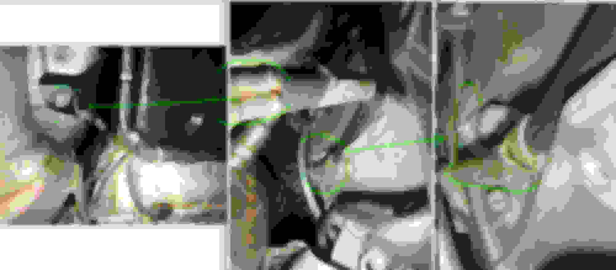
W-TF ground on mine and a W204 C200 with M271.8 of 2010 is similar location . I would think M278 and M157 would be similar, but M177 of GTR I have no clue.
My car is RHD , Righ Hand Drive , opposite to US cars being a LHD.
Photo above is at the LEFT side exhaust pipe.
.
.
.
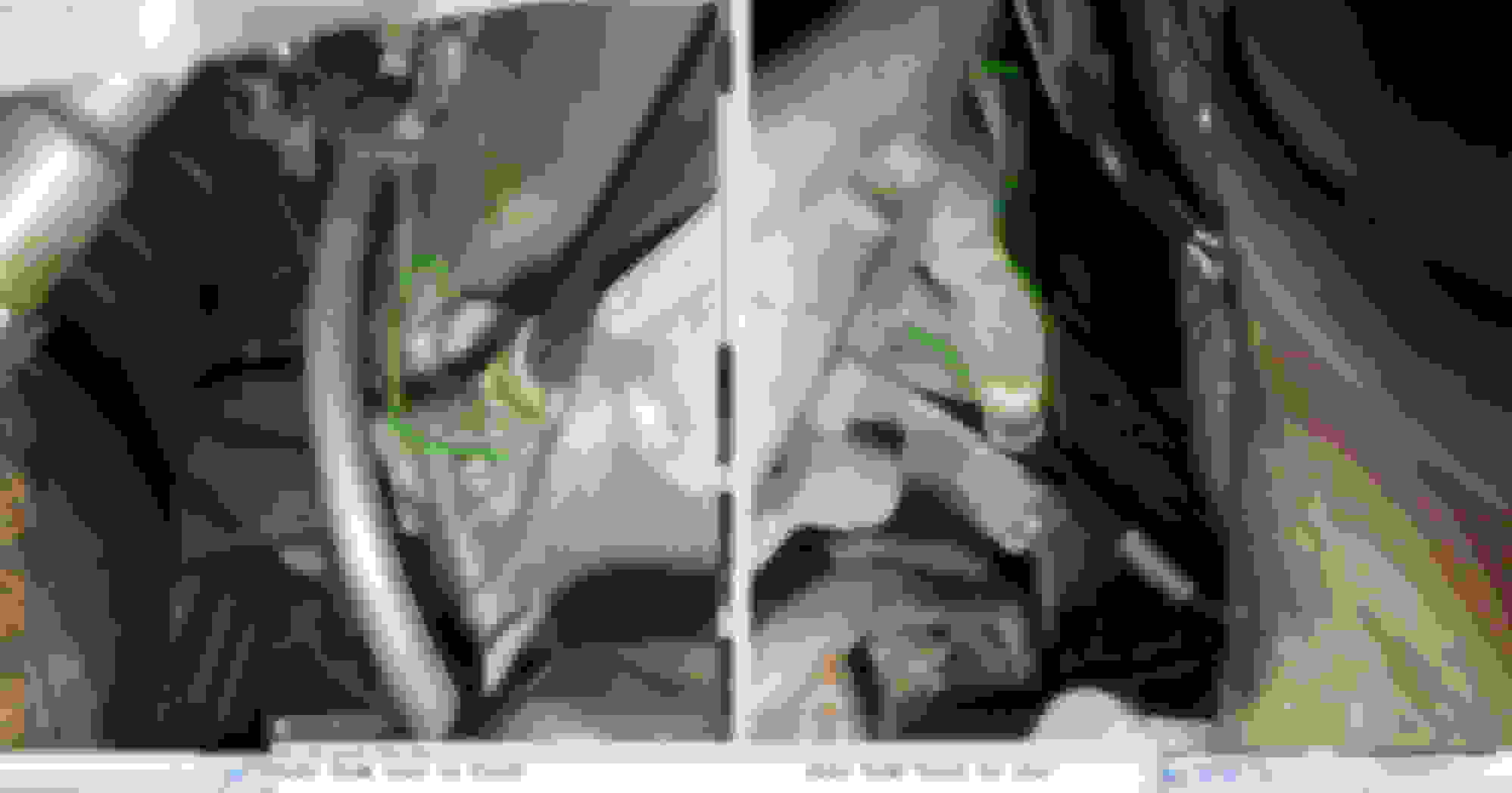
I love the fact that MB ground cable/eyelet, be it small or biggest one, they are crimped and soldered.
Toyota 2020 Corolla Cross and even Land Cruiser 300 of 2024 are only crimped, no extra soldering.
Ford Fiesta of 2010, only crimped too.
MB ground stud is MALE and is not painted at contact surface , with a bit of wide base, this is good.
Most other cars uses female thread instead, a bi-etch to clean and no wide unpainted surface, unless you remove the paint.
In country with winter salt, grounding wire like below is the worst kind.
M157 / M278 COP, same wiring or pin assignment with M276.8 or .9
Observe wire sizing, it tells a lot of the duty of the pin number.
Pin 1 , 0.5mm mini wire, to W16/5 Signal Ground
Pin 2, 1.5mm thicker wire to W11 Power Ground
Pin 3, 1.5 mm thicker wire to Fuse XX for Positive Power, 1 fuse serves 1 bank or 4 COPs if a V8.
Pin 4, 0.5mm mini wire from ECM to send the 5V trigger signal to fire the COP
My visualization of our COP, based on my M276.820 wiring
The Pin #3 and #4 no need to discuss in depth. They are simple in its wiring.
The Pin #1 and #2 need deeper discussion.
Pin #2 is 1.5mm thicker wire to W11 Power Ground, but its amperage load is not actually handled a 100% by this 1.5mm cable, but the bulk of it is handled by one of the metal ring of COP,
where it will touch cylinder head as power ground. Above image based on COP, W11 or pin #2 gets to handle only 4.6 amps out of the total 19.7 amps.
Arrow B in red is the said metal ring as Power Ground from cylinder head.
On my COP, I got extra needle like contact point , aside from the metal ring as 2nd way to touch and get better contact to cylinder head as Power Ground.
It is easy to confirm that pin #2 to W11 is also connected to the metal ring B of M278/M157 COP, test it with DMM using Ohms or contiunity.
I have tested mine below.
Note on Pin #4, which the fuse number is probably different if M278 / M157.
Observe below, pin #1 and in #2 is not connected or common, albeit both are supposedly "Ground".
Thus we need to understand the function of Pin # 1 to W16/5 Signal Gound for COP vs Pin #2 , W11 Power Ground of COP.
At first I was kinda confused, as there is no proper literature in WIS on the 100% actual working of our COP having 2 "ground" wires/connection.
The W11 pin #2 is easy to understand as Power Ground, because when measured with a current clamp , it shows the current flowing thru it, albeit only 4.xx amps due to
COP metal ring B carrying the rest of the current. See below, after cleaning the ring and the needle, the W11 wire only get to carry a bit under 4 amps out of the total 19.xx amps.
.
Pin #1 , the W16/5 does not carry any amperage load during COP firing, see below :
Channel D in brown is current clamp for Pin #1 ( W16/5 ). Nil current flowing thru it, while Pin #3 Positive Power from fuse XX is loaded to 19.xx amps.
This is why I called Pin #1 to W16/5 is Signal Ground and not Power Ground.
The other fact which initially confused me is that, the ECM uses W16/5 as Power Ground, 3 wires served as Power Ground to ECM F connector pin 2, 4 and 6.
The biggest size pin or terminal at ECM 2 of connectors assy, is the F connector 6 pins, Negative or Power Ground being pin 2, 4 and 6,
and Positive Power being pin 1, 3 and 5.
Only when I tested engine running and disconnected Pin #1 wire ( from W16/5 ) to COP, there then its very clear as to why MB wired Pin #1 of COP to the W16/5 .
The Pin #1 of COP produces Signal to tell ECM that COP is firing, by way of Signal Ground wire to be paralleled or joint/spliced to Power Ground of ECM thus less inteference from other components.
See how misfire occured the moment I disconnected the wire from W16/5 of Pin #1 of COP.
I made specific COP test wire kit for this purpose.
.
-------
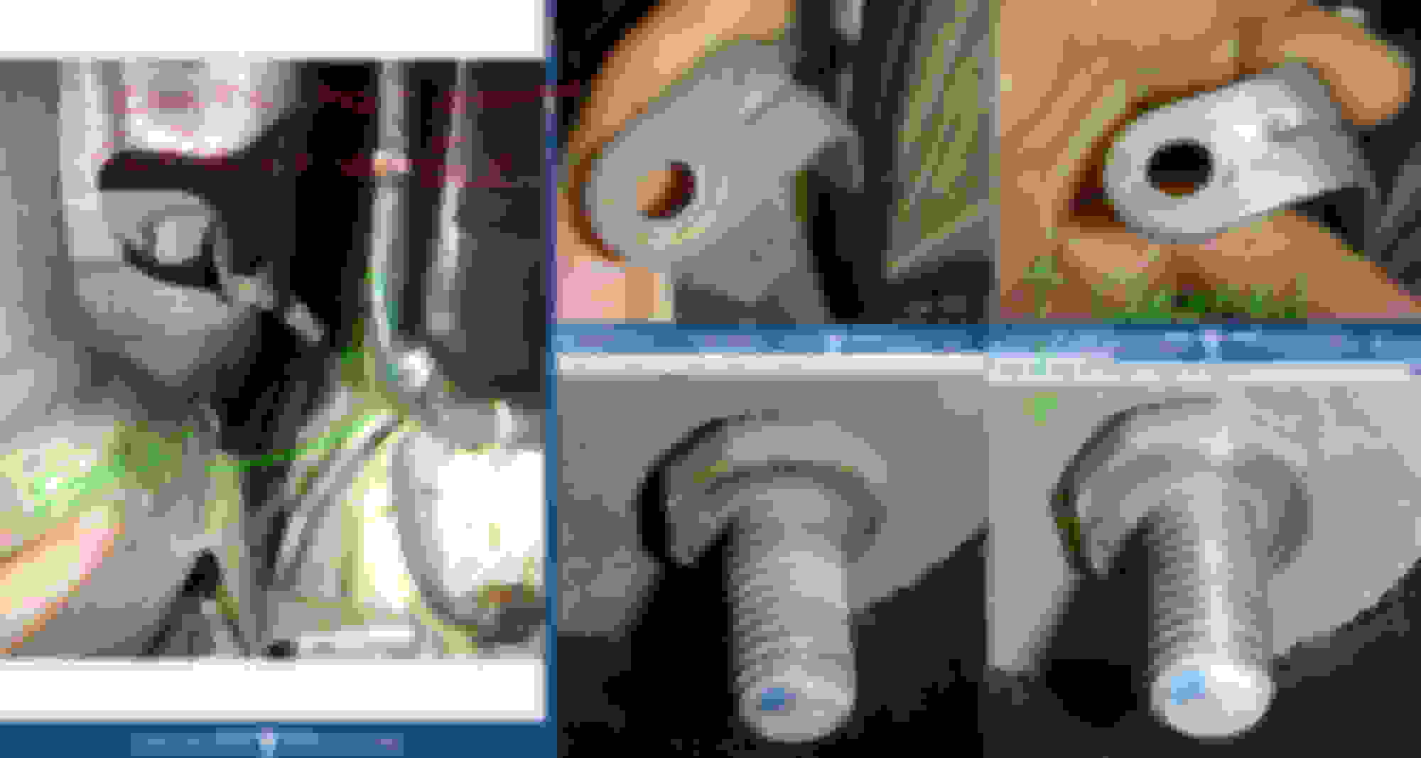
This is my W16/5 , confirmed thru testing. Remember, mine is a RHD car, not LHD. It is at firewall side of battery tray or HVAC air blower fresh air intake.
I can't be sure if W16/5 stud position is the same between RHD and LHD car. I have seen interior ground studs which its ID number is the same but its position is opposite.
MB WIS is based on LHD cars, so me at a great loss because I get f--ked all the time when it comes to actual position of ground stud aka many locations are wrong for RHD car.
Cali said it is most likely W16/5 on LHD car is behind the brake booster, thus it is actually by position is very similar to my RHD car.
.
Total number of wires of W16/5 eyelet is 5, not 4.
3 for ECM, 1 for COP set and 1 more is for OBD/DLC port . MB called this port as X11/4.
-----------------------
Now, in 1st post I said Pay attention to the X26 #1 interconnect connector where W16/5 becomes Z6z1.
On my engine, X26 no 1 is a big interconnect connector, see below : I believe on M276.9 , M278 and M157 it would probably be the same type of connector used, because the pin used for W16/5 is 9th pin for M278 / M157
Thus the connector is likely below's 13 pins connector.
This connector would be between engine side close to Front SAM, for LHD car its probably at Bank 2 azz.
On my RHD car it is at Bank 1 azz.
Anytime an interconnect connector is used, the risk of poor or intermittent bad contact is higher than a connection using soldered eyelet secured down by Hex Nut size 10mm, as in W16/5 ground stud.
Inspect and clean this X26 no 1 of your engine.
What does this X26 no 1 interconnect connector is handling ? All the VIP power and Grounds
.
Thus now knowing X26 no 1 interconnect connector pin 9 is where all engine COPs pin #1 Signal Ground is routed thru before becoming W16/5, respect its importance towards
misfire prevention .......which is not based from Power Ground, but from loss of Signal Ground of COPs firing for the ECM.
End of post.... hope this will be useful.
Last edited by S-Prihadi; Dec 24, 2024 at 11:58 AM.
Reason: typo
Merry Xmas to those celebrating it and soon Happy New Year to all .
00:50 AM Bali time now, 25th Dec 2024. So it is already Christmas for me ....
Merry Christmas to you and your family, be safe and healthy, and merry Christmas too @CaliBenzDriver , both of you are always amazing at being so supportive and providing great contributions to this forum
"Our Actions Speak Louder Than Our Words!" to wish you :
a great Holiday season
a merry Christmas
a great new Year '25
We've got more exciting bug fixes, coming up to make your Mercedes run better than new for free.
The topic will be further cancelling the artificial chaos used to make the CAN-Bus Xfers *quietly* unstable.
The results are further reliable strong Mixtures + predictable powerful Shifts + excellent Batteries = makes Mercedes great again!
Reduced wear with more power skillfully disabled from factory.
Many thanks to Master Surya, MBW friends and great contributors.
Gift to self: unplug ALT LIN! ⛄🎁🎄
Last edited by CaliBenzDriver; Dec 24, 2024 at 07:04 PM.
Welcome to the Alternator LIN un-plug club , you will love it.
- No more crazy POSITiVE high amperage into battery after cranking and engine then running.
- No more voltage at battery less than 13.8 volts , except first 1-2 seconds when and if electric power steering in full power mode ( 80 ish amps ) during tight parking manuvers.
- No more high amperage discharge on battery when engine is running. Bear in mind typical alternator response is about 2 seconds to sudden big load change.
- Excellent current/amperage regulation up to 0.2 amps at 13.9V when battery is already full when engine is running. This is float voltage/current territory only good-smart alternator can do.
- Most likely you can do at least 4 hours of music at relaxed volume, engine OFF when and if your car battery is still healthy at 80Ah...without the SAM low voltage protection algo taking over and kill the audio system.
I wanna join this club! �just gotta figure out my wiring on the m157 e63s! One day maybe we can deep dive the wiring schematic for my model�I swear that two wire plug was the back side of my alternator!
I wanna join this club! �just gotta figure out my wiring on the m157 e63s! One day maybe we can deep dive the wiring schematic for my model�I swear that two wire plug was the back side of my alternator!
I pulled the plug by feel blindly. I could see anything despite use of angled mirror-stick...
Single wire connector is located on the back side of ALT facing firewall (not on the 1" plastic edge of ALT. nothing there)
Power down the chassis Batt. GND to reboot
Remove watever is in the way for access (air filter pipes...)
Locate connector by feel...
Pull the connector lock tab
Press on extended tab to release lock while backing out connector
(optionally protect open junction - I did not)
Reconnect batteries GND to complete reboot
Scan and reset faults (never mind ECU: Pump! + ALT!)
Welcome to the Alternator LIN un-plug club , you will love it.
- No more crazy POSITiVE high amperage into battery after cranking and engine then running.
- No more voltage at battery less than 13.8 volts , except first 1-2 seconds when and if electric power steering in full power mode ( 80 ish amps ) during tight parking manuvers.
- No more high amperage discharge on battery when engine is running. Bear in mind typical alternator response is about 2 seconds to sudden big load change.
- Excellent current/amperage regulation up to 0.2 amps at 13.9V when battery is already full when engine is running. This is float voltage/current territory only good-smart alternator can do.
- Most likely you can do at least 4 hours of music at relaxed volume, engine OFF when and if your car battery is still healthy at 80Ah...without the SAM low voltage protection algo taking over and kill the audio system....
Merry Christmas -
Totally agree: you'll love this all year round.
The very first thing that striked me was my engine idling higher at operating temperature. Idle is usually well controlled.... so I was surprised!
W212 runs better on fixed VOLTAGE more so than variable [12.6V to 14.9V] design range.
This means Chassis Is Indeed Voltage Sensitive.
Be it pump, injectors, coils or networking: normal voltage registers an Rpm difference until ECU re-normalize things.
Its a sad joke that Bosch is NOT compatible with its own technology - One would think chassis would be compliant with variable voltage: this proves it is not!
Chassis has to relearn stable 14.2V supply:
Tranny shifts
Engine idle Rpm
Electric steering
LED Head lights
CAN-bus tranceivers
....
This means the variable voltage is directly a chaos factor not tolerated transparently by chassis.
It negatively impact operations:.... not just a little!!
I gave Bosch full credit of No1 world leader, thinking ECU would tolerate well operation regardless of voltage: HELL NO!
It's just like you know it:
voltage affects everything electrical remains 100% true here!
Having variable voltage screws up every module that's adaptable because chassis is NOT COMPATIBLE WITH VARIABLE VOLTAGE.
An honestly compliant module would have voltage correction factors...
Now voltage swings are tolerated as chaos factors.
> UNSTABLE CAN buses :
Ultimately what I am seeking is stable CAN-bus operations to try cancelling chassis moodiness. The type that benefits bi-monthly reboots.
CAN-Bus tranceivers have some learning ability to adapt to a range of differential voltage levels.
I have recently discovered CAN-B+C+... are also artificially jacked up with multiple signal levels on the same network... harder/impossible to adapt to a range of levels made extreme.
I need to experiment rewiring the nodes hanged on the F-SAM that are made harder to reach.
Practically this means CAN bandwidth is forced down by artificially poor nodes. That's why fixing solderless modules delivers performance increase...
TeamSurya has more great fixes coming.
Merry Christmas
🎄⛄❄️
++++ MB COMBO... YO-YO for 90Amps shots!
-- When Rear-SAM/CAN-B disruptions are bad enough ECU quits commanding ALT due to corruption.
-- Chassis voltage drops into extremes 12v, 11v, 10v, ...
-- Personally I no longer have 90Amp battery killer yo-yo which ALT LIN does prevent regardless of CAN disruptions.
+++ INDEPENDENTLY SMART REGULATOR !!
-- It has its own current shunt to measure load
-- Obviously regulator measures the output voltage
-- What it ignore is "battery internal temperature" reported by Hyundai sensor... I don't think it's an issue while battery charge current is small under 10A: small.
-- Q: can 14.15v boil off hydrogen from old AGM vs. 90Amp uncontrolled YOYO... your pick
-- Nice side effect: ECU now automatically disables ECO
Last edited by CaliBenzDriver; Dec 25, 2024 at 05:31 PM.
I wanna join this club! �just gotta figure out my wiring on the m157 e63s! One day maybe we can deep dive the wiring schematic for my model�I swear that two wire plug was the back side of my alternator!
From Tasos channel - M157
Connector is REAR ENTRY / FACING, It seems 180amps model, sticker is there.
Also if we decide to do this, is it necessary to remove negative batt cable first? Or can we just disconnect the connector on the side of alternator and that is it?
Do we need to clear any codes as well? I don't have mercedes specific scanner...
Also if we decide to do this, is it necessary to remove negative batt cable first?
Or can we just disconnect the connector on the side of alternator and that is it?
Do we need to clear any codes as well?
I don't have mercedes specific scanner...
Disabling UNSTABLE VOLTAGE is beneficial to all chassis that are barely tolerant with it instead of really being compliant... good chance it's also true on other makes...
If applicable, you can simply pull ALT LIN and be done but personally I power cycle ("REBOOT") the chassis to enable all the modules to automatically readapt their CAN transceiver voltages for full bandwidth speed.
ECU is going to flag the new LIN circuit fault that will not clear while it remains actively disconnected.
I have both "Pump MOD" + "ALT LIN" active faults without CEL.
You don't need an MB scanner but having one will come in handy to see what modules are flagging errors... unrelated to stable voltage.
It's not the voltage alone we're after, it's the stable networking bandwidth between ECU - TCU - ... ESP/CGW/SAM.
Last edited by CaliBenzDriver; Jan 7, 2025 at 12:39 AM.
Why do you think the engineers designed the car this way?
Why does MB design cars with many systems built to be marginally functional ??
It's to field stress-test their systems before licensing them to partner makes couple years later.
Realize all our premium electronics are available on Toyotas & Hondas with perfect records, real cheap.
Extreme conditions are artificially created to see how modules perform against the odds.
The ECU sitting on top of V8 valve covers or V6 exhaust pipes is less favored by Japanese who prefer the cabin location near SRS. The list goes on with solderless oxidation....
We signed up for Mercedes bleeding edge, doesn't mean we like juggling with short sticks.
We can peel back this onion to make core systems run flawlessly!
Last edited by CaliBenzDriver; Jan 7, 2025 at 01:19 AM.
Why does MB design cars with many systems built to be marginally functional ??
It's to field stress-test their systems before licensing them to partner makes couple years later.
Realize all our premium electronics are available on Toyotas & Hondas with perfect records, real cheap.
Extreme conditions are artificially created to see how modules handle extremes.
The ECU sitting on top of valve covers or exhaust pipes is less favored by Japanese who prefer the cabin location near SRS. The list goes on....
We signed up for Mercedes bleeding edge, doesn't mean we like juggling with short sticks.
We can peel back this onion!
but year after year they're still engineering it this maladaptive way? When do they (Mercedes) deliver the Toyota perfect record of reliability? Why is the ecu always on the engine (aka convection oven)?
-- but year after year they're still engineering it this maladaptive way?
-- When do they (Mercedes) deliver the Toyota perfect record of reliability?
-- Why is the ecu always on the engine (aka convection oven)?
It's all about pushing the envelope to test the limits - A turbo V8 with aluminum bores... seriously?
- low oil pressure random squirting under 3500.Rpm... seriously?
- Artificially uneven CAN branches operating under unstable voltage... not for me!
Mercedes is a luxury brand because of its amazin' cost of ownership. It's not supposed to compete with Lexus reliable branding.
Instead of managing functions, engineers track disfunctions to provide gentle failures modes that aim to remain safe.
Like the Bosch solderless ABS/ESP crown jewel or the solderless electric steering assist. It must go down gently without injuring customers.
It's trivial to factor out managed chaos for licencing. Very little unknown randomness.
The ECU location is unfavorable to prove what it can handle under various stressors. High voltage spikes harnesses near low-signal sensors
The solderless Bosch ESP can run well if enough pressed pins share the power ...
- else soldered Bosch ECU works perfectly in the harshest hot engine locations.
If I had one wish... would be to keep the rain water out of our electricals.
+++ PARTS OF THE FORMULA...
So far what stands clear is CAN Networking is woven into every interconnected modules. Improving CAN improves everything, especially VIP's on fast CAN's: ECU + TCU + ISM
What's clear is instabilities factors are used to tank powertrain performance. The chassis is transformed with just a few tweaks.
CAN bandwidth is like a data fuel pipe. Bosch choose to make ECU core timings vulnerable to precise data delivery then made it elastic
I do not have measured number... instead I evidenced that when the network is under improved conditions so is the engine.
So I keep improving data networking with this :
solderless modules poor connections
variable voltage references (floating GND/VCC)
Hardly compatible CAN branch impedances
Everything I've done goes in the same direction towards STABLY PREDICTABLE POWERTRAIN TIMINGS is what ECU really enjoys
From the crank rotation to CAN timelines.
-- Some types of Misfiring are linked to timing latencies. Feel free to try "stable voltage" to cancel randomness.
-- Same is true for "lean under acceleration..."
-- You'll find out right away as things get improved.
Instant gratification with free self-tuning ECU/TCU.
This is becoming "The Best Or Nothing" we were in search of.
Last edited by CaliBenzDriver; Jan 7, 2025 at 03:30 AM.
Mercedes SLR McLaren 722 S Is Extremely Rare Example Modified by McLaren
Slideshow: A one-of-one U.S.-spec Mercedes-Benz SLR McLaren Roadster became even rarer after a factory-backed transformation at McLaren's headquarters.


 .
. 


